Vulkan
Starting
Versions
-
Versions and Features Breakdown .
-
Patch notes.
-
-
Why not use Vulkan 1.0? {12:57 -> end} .
-
1.0 is harder, with missing features and clunky interfaces.
-
The video is pretty nice. I listed the problems it explained about 1.0 and placed them in the documentation below.
-
It was well explained and I came to appreciate using Vulkan 1.3+.
-
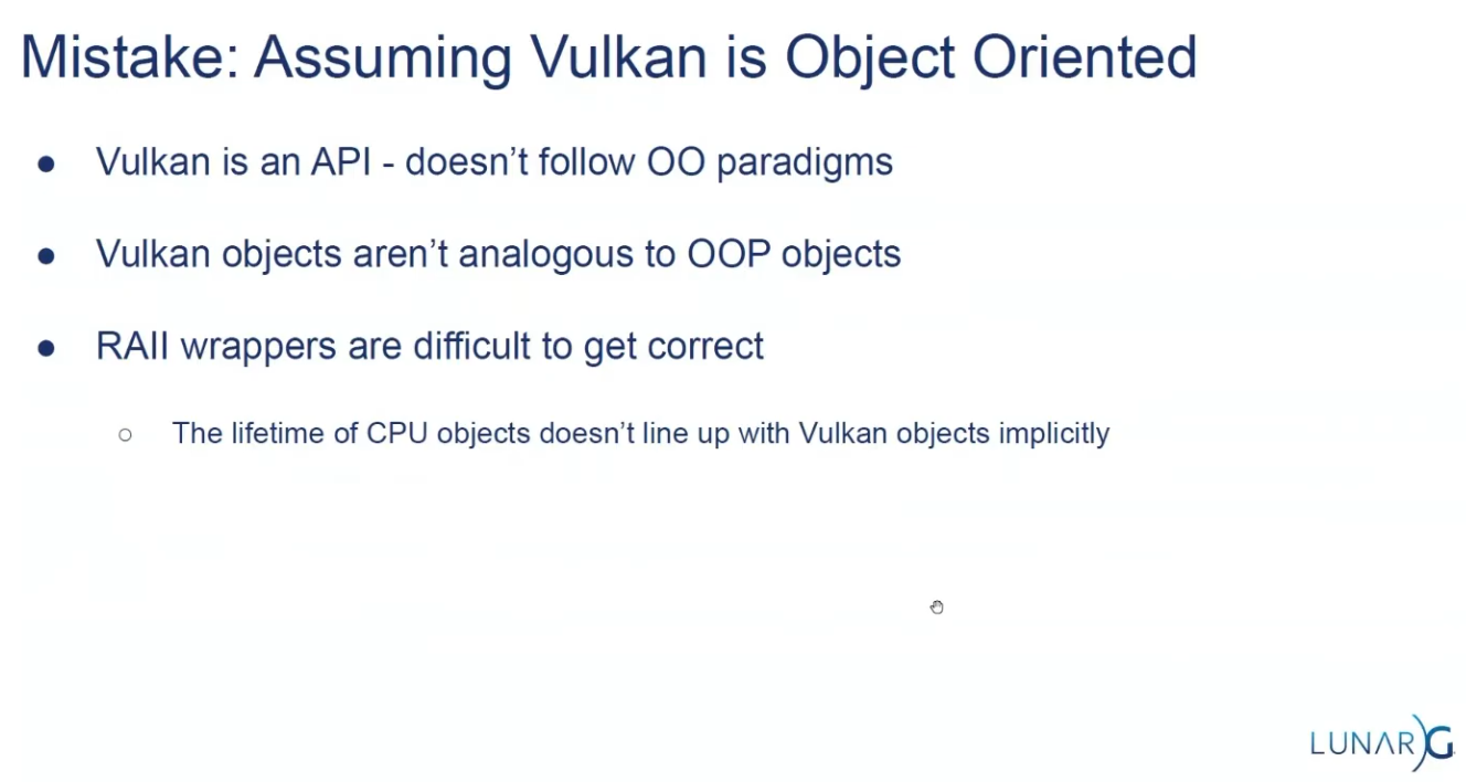
Is OOP?
-
Version 1.3, (2024-02-22).
-
 .
.
API Structs
-
Many structures in Vulkan require you to explicitly specify the type of structure in the
sTypemember. -
Functions that create or destroy an object will have a
VkAllocationCallbacksparameter that allows you to use a custom allocator for driver memory, which will also be leftnullptrin this tutorial. -
Almost all functions return a
VkResultthat is eitherSUCCESSor an error code. The specification describes which error codes each function can return and what they mean. -
The
KHRpostfix, which means that these objects are part of a Vulkan extension. -
The
pNextmember can point to an extension structure.
Compatibility
Support
-
Windows (7 and later)
-
Yes, via the official SDK and drivers.
-
-
Linux
-
Yes. Native support via Mesa and vendor drivers.
-
-
Android (5.0+)
-
Yes, most devices from Android 7.0+ support Vulkan.
-
-
macOS
-
No native support — requires MoltenVK (Vulkan-to-Metal wrapper).
-
-
iOS
-
No native support — requires MoltenVK.
-
-
Web
-
No native support — experimental via WebGPU or Emscripten with translation layers.
-
-
Consoles.
-
Partially supported; depends on platform SDKs and NDAs (e.g., Nintendo Switch uses a Vulkan-like API).
-
Driver support
-
Vulkan requires updated GPU drivers.
-
Older or integrated GPUs (especially pre-2013) may lack Vulkan support.
-
Vendor support varies: NVIDIA, AMD, and Intel generally support Vulkan on most modern hardware.
Compatibility Layers
-
To increase compatibility.
-
MoltenVK :
-
Runs Vulkan on Metal (required for macOS/iOS).
-
-
gfx-rs / wgpu / bgfx :
-
Abstraction layers to use Vulkan when available, fallback to other APIs.
-
-
ANGLE / Zink :
-
Can translate other APIs (e.g., OpenGL) to Vulkan and vice-versa.
-
Tutorials
Tutorials in Docs
-
-
I already read everything before the memory allocation section.
-
-
-
Based on the vulkan-tutorial, with differences:
-
Vulkan 1.4 as a baseline
-
Dynamic rendering instead of render passes
-
Timeline semaphores
-
Slang as the primary shading language
-
Modern C++ (20) with modules
-
Vulkan-Hpp with RAII
-
It also contains Vulkan usage clarifications, improved synchronization and new content.
-
"This tutorial will use RAII with smart pointers and it will endeavor to demonstrate the latest methods and extensions which should hopefully make Vulkan a joy to use."
-
-
Does not require knowledge of previous APIs, but you need to know C++ and graphics math.
-
Impressions :
-
Holy moly the new C++ API is a pain.
-
I preferred to go back to the vulkan-tutorial several times and check how it's used in the C API.
-
I used this tutorial only as a base to consider the new features.
-
I didn't use Slang, I didn't like it; I stayed with GLSL.
-
-
-
-
Does not require knowledge of previous APIs, but you need to know C++ and graphics math.
-
You can use C, but the tutorial is in C++.
-
Vulkan 1.0; shown here .
-
Uses GLSL for shaders.
-
-
~ Vulkan Guide .
-
For people with previous experience with Graphics APIs.
-
I'm not a big fan of this guide.
-
Uses :
-
Vulkan 1.3.
-
C++, Visual Studio, CMake.
-
SDL to create a window.
-
-
Abstracts a big amount of boilerplate that Vulkan has when setting up. Most of that code is written once and never touched again, so we will skip most of it using this library. This library simplifies instance creation, swapchain creation, and extension loading. It will be removed from the project eventually in an optional chapter that explains how to initialize that Vulkan boilerplate the “manual” way.
-
-
-
Implements memory allocators for Vulkan, header only. In Vulkan, the user has to deal with the memory allocation of buffers, images, and other resources on their own. This can be very difficult to get right in a performant and safe way. Vulkan Memory Allocator does it for us and allows us to simplify the creation of images and other resources. Widely used in personal Vulkan engines or smaller scale projects like emulators. Very high end projects like Unreal Engine or AAA engines write their own memory allocators.
-
-
-
Impressions :
-
The tutorial gives you a project with many things already done, and holds your hand for every syntax, file, folder, methodology, etc.
-
It simply throws a lot of stuff at you.
-
It's a pretty bloated experience, for sure.
-
I consider that a pain.
-
-
-
Playlists
-
Playlist Vulkan with Odin - Nadako .
-
Vulkan 1.3, with Dynamic Rendering.
-
I watched videos 1 through 11.
-
They are good videos.
-
I do not recommend them to someone who has never seen anything before, because they are not exactly for beginners and their explanations lack some foundation.
-
I recommend them as a reference for how to set up in Odin.
-
-
-
C++, with Visual Studio.
-
Assumes you have seen another GPU API before.
-
Video 1:
-
Window with GLFW, not explained.
-
-
Video 8:
-
Theory explanation ok; code explanation meh.
-
-
Video 12:
-
Synchronization with 1 frame in-flight.
-
Good video.
-
-
Video 16:-
Descriptor Sets.
-
Nope. See the spec, guides, or other videos on the subject, I think it's better.
-
-
Video 21:
-
Dynamic Rendering.
-
{0:00 -> 12:14}
-
Explanation of the code to obtain the EXT for Vulkan 1.2, and ignore it for Vulkan 1.3
-
-
The rest of the video is irrelevant, it does not explain anything beyond what to change if someone is following his code line by line.
-
-
-
Playlist Vulkan 2024 - GetIntoGameDev.-
Overall :
-
The person seems nice and I like when he draws things.
-
Unfortunately 95% of the series videos are code in C++ and he does not do a good job explaining the code.
-
I listed some videos below that I considered interesting.
-
-
Vulkan 1.3.
-
Video 12:
-
Synchronization, with 1 frame in-flight.
-
The drawings are nice.
-
-
~Video 13:
-
Multithreaded rendering.
-
Nope. See the Multithreading Rendering section to understand why "nope".
-
-
Video 26:
-
Barycentric coordinates.
-
-
Only code, so nope :
-
Videos: 9, 10, 14, 15, 16, 17, 18, 19, 20, 21, 22, 23, 24, 25, 27, 28, 29.
-
-
Playlist Vulkan - GetIntoGameDev.-
Vulkan 1.2, (2022-01-22).
-
Watch the new 2024 version of the tutorials.
-
The person sometimes explains on a sheet of paper, which is nice.
-
-
-
Playlist Vulkan - Computer Graphics at TU Wien.-
Vulkan 1.2.
-
Video 1:
-
SDK, Instances, extensions, physical devices, logical devices.
-
Ok.
-
-
Video 2:
-
Presentation Modes, Swapchain.
-
{10:20 -> 21:45}
-
Explanation of all Presentation Modes.
-
-
-
Video 3:
-
Explanation of Buffers and Images.
-
The explanation seemed s a bit rushed and the definition is poorly established.
-
I can return and rewatch the video after reading the documentation.
-
-
Video 4:
-
Commands, Command Pools, Command Buffers.
-
Ok, sure.
-
I skipped the descriptor sets part.
-
-
Video 5:
-
Pipelines.
-
I skipped it.
-
-
Video 6:
-
Synchronization.
-
Skipped.
-
-
Impressions :
-
I don't like the illustrations, nor the tone of the explanation.
-
I simply feel I learn more and feel more confident reading the documentation or the spec.
-
The videos are "more technical", but when that is the case documentation is better.
-
I prefer a simpler playlist to learn some basic concepts, and to read the documentation for advanced topics.
-
-
-
Playlist Vulkan - Brendan Galea.-
Vulkan 1.0.
-
C++, with Visual Studio.
-
It's a pain to see C++ code.
-
The sketch explanations in the middle of the videos are ok, but the rest is very bad; all code-related parts are unpleasant and with a LOT of mess in C++.
-
Video 1:
-
Window with GLFW.
-
-
Video 2:
-
Light explanation of the graphics pipeline.
-
{9:54}
-
Shader compilation, to SPIR-V.
-
-
-
Video 20:
-
Descriptor Sets
-
{0:00 -> 5:35} Nice explanation.
-
The rest of the video is nah.
-
-
-
-
C++
-
Starts by teaching how to install Visual Studio and Git...
-
Does not use GLFW, instead creates its own platform layer on Windows to create a window.
-
-
Vulkan playlist - Francesco Piscani.-
He uses the vulkan-tutorial.
-
Spends the first 4 episodes doing basically nothing, just setting up CMake and Linux.
-
Nope, it sounds bad as tutorials.
-
Talks
-
-
Use RenderDoc extensively.
-
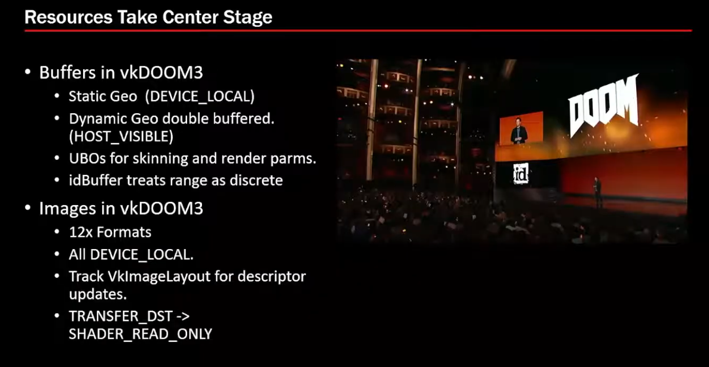
1 Render Pass, 1 subpass, 3 attachments.
-
 .
.
-
-
Buffers and Images
-
 .
.
-
-
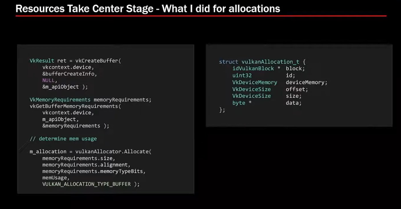
Allocations:
-
VMA for allocators.
-
 .
.
-
 .
.
-
-
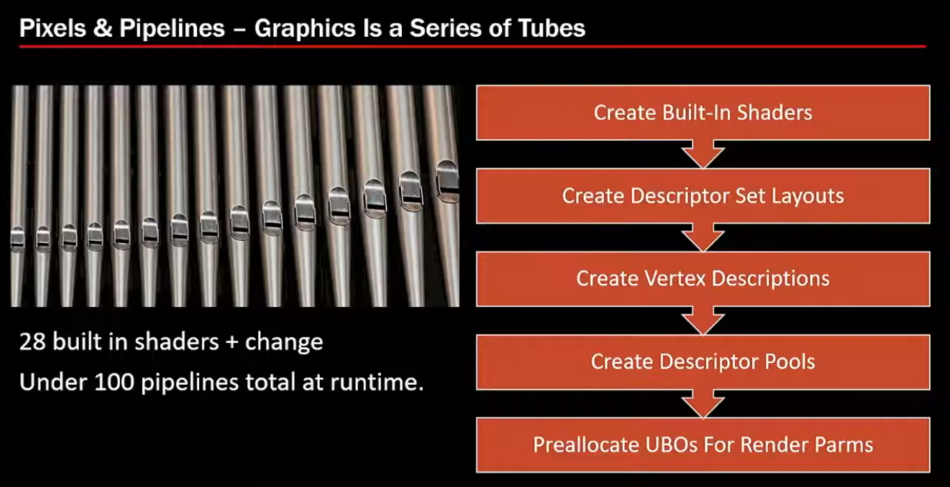
28 shaders + changes => 100 pipelines total at runtime.
-
 .
.
-
-
Synchronization:
-
Not much of it. Doom 3 was single-threaded, it didn't require multithreading.
-
-
Samples
-
To run :
-
Git clone recursively the repo.
-
Build the entire solution.
-
Vulkan-Samples\build\windows\app\bin\debug\AMD64. -
Copy the
shadersandassetsfolders fromVulkan-Samplesto the folder above. -
Type
.\vulkan_samples sample sample_name.
-
-
Note :
-
Normal and hpp have the same performance; or whatever, it does not matter.
-
-
Impressions :
-
The extension samples were more visually "uninteresting".
-
I saw all API samples, but I didn't see all Extensions.
-
There were still other folders besides these two, but I was lazy to check.
-
API
-
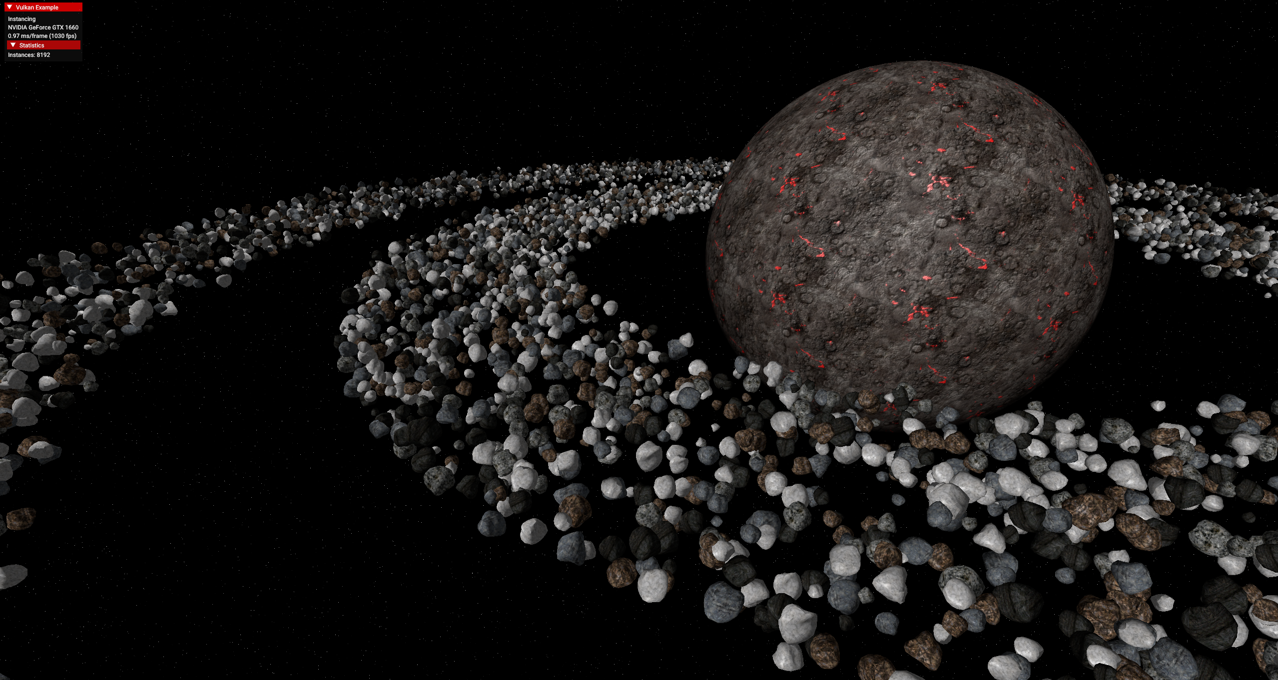
instancing
-
 .
.
-
Wow, awesome.
-
The fps is very high.
-
-
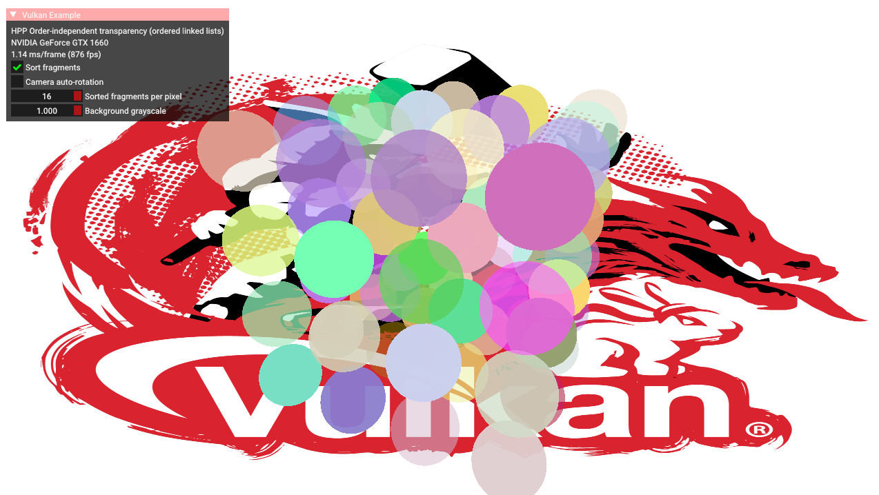
oit_linked_lists (Order Independent Transparency)
-
 .
.
-
-
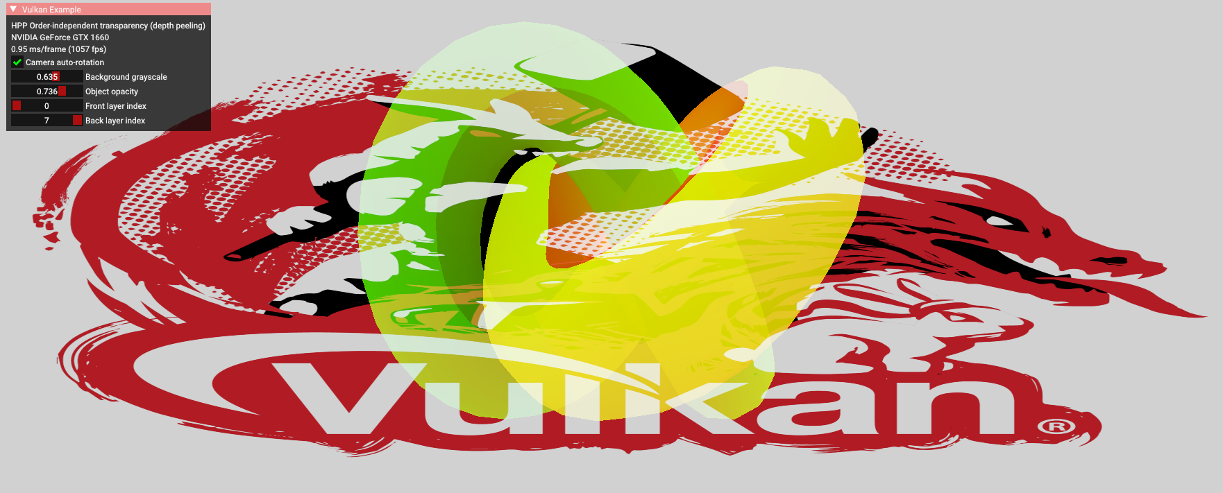
oit_depth_peeling (Order Independent Transparency)
-
The object in the center rotates with the mouse.
-
 .
.
-
-
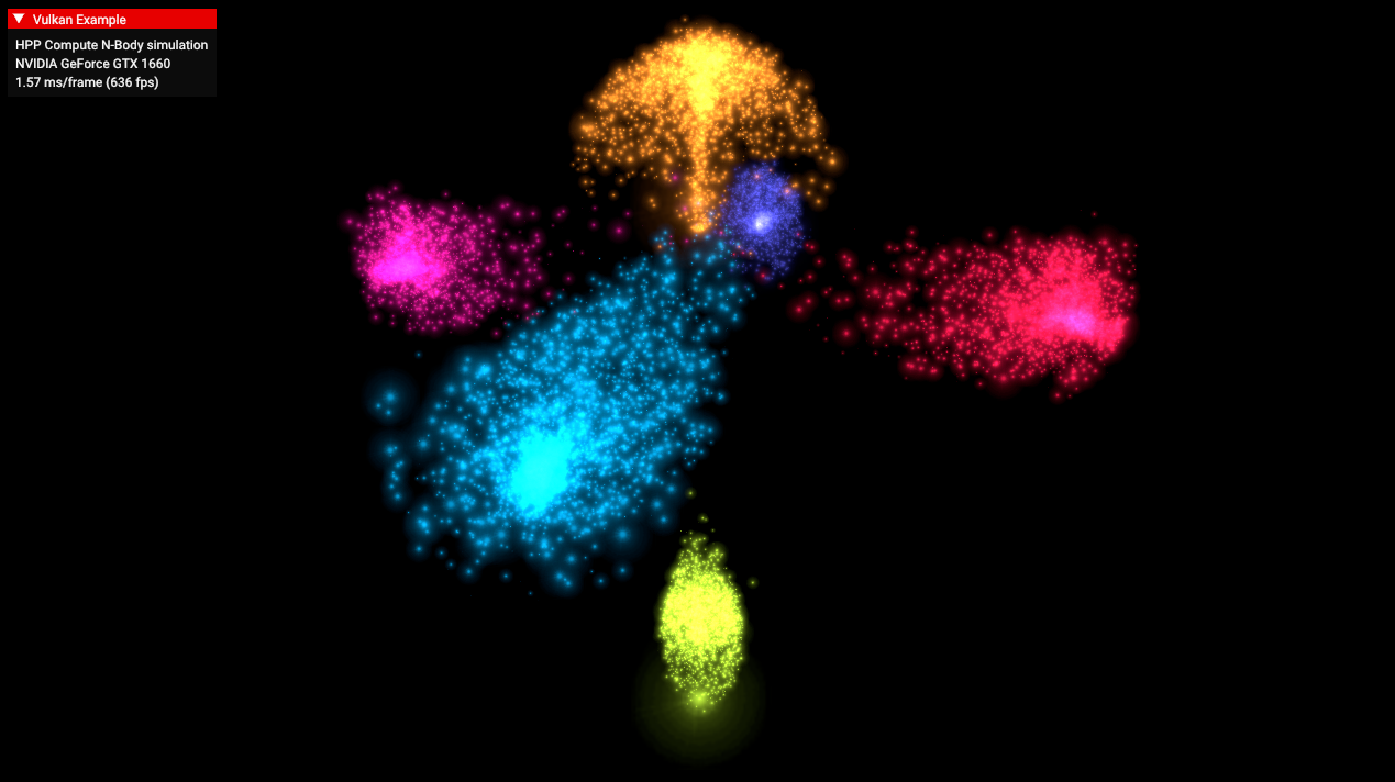
compute_nbody
-
 .
.
-
-
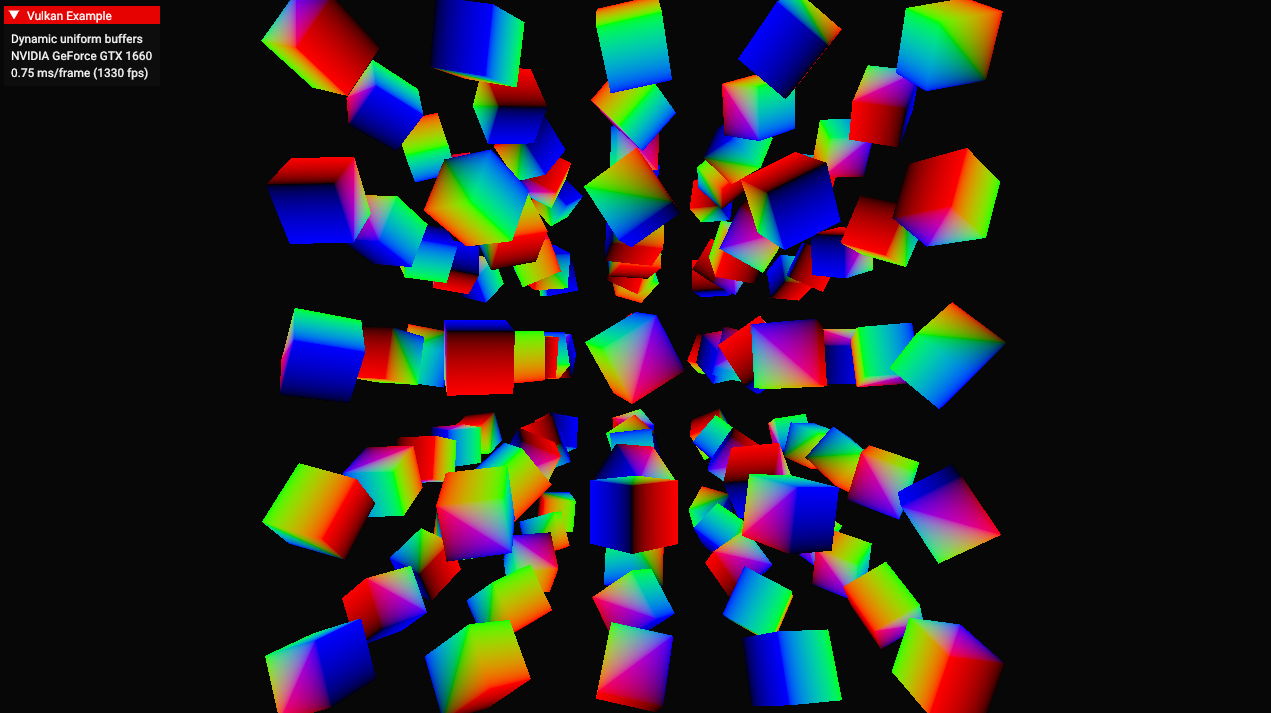
dynamic_uniform_buffers.
-
 .
.
-
-
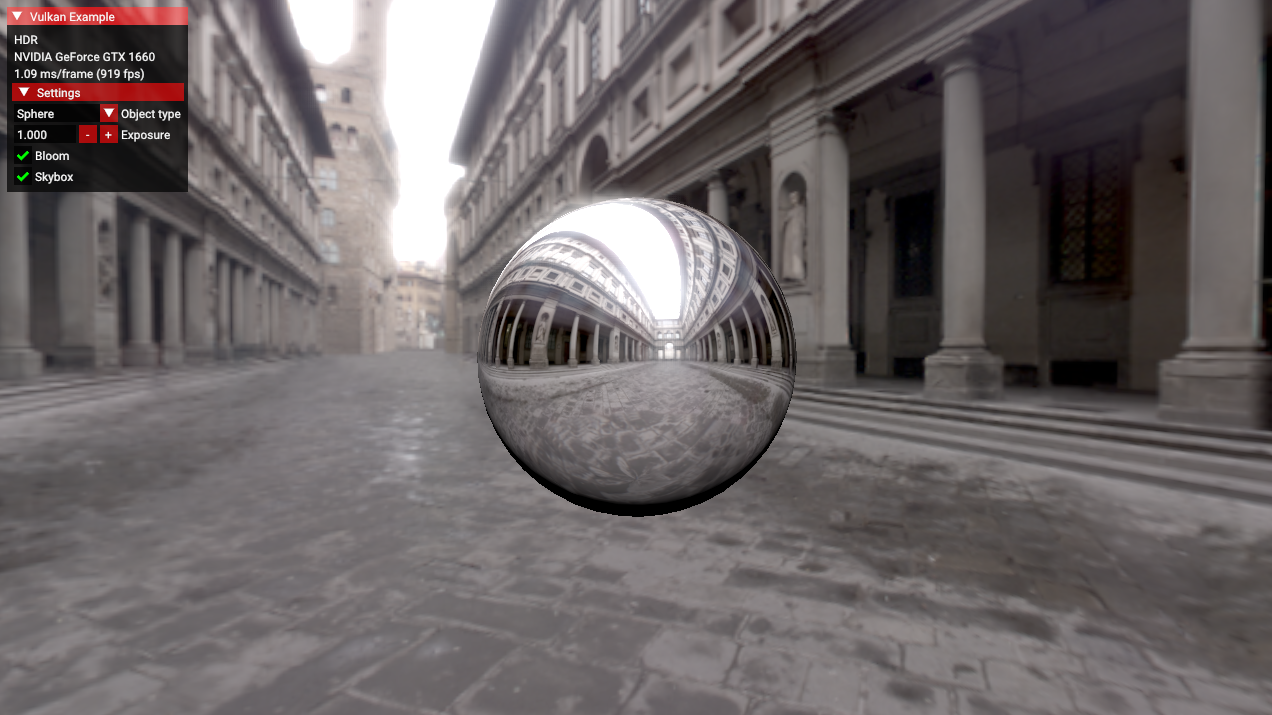
hdr
-
 .
.
-
Allows changing the object, toggling the skybox, changing the exposure, toggling bloom.
-
-
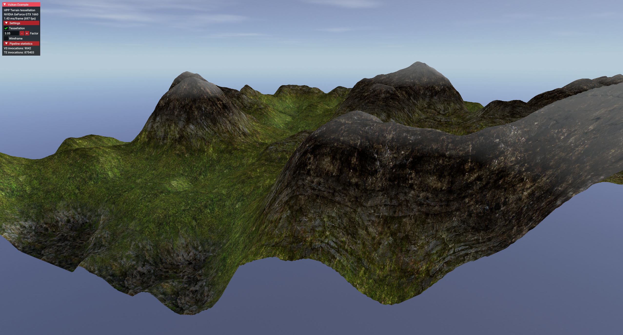
terrain_tessellation
-
 .
.
-
Increasing the tessellation factor made it look like the terrain polycount increased.
-
-
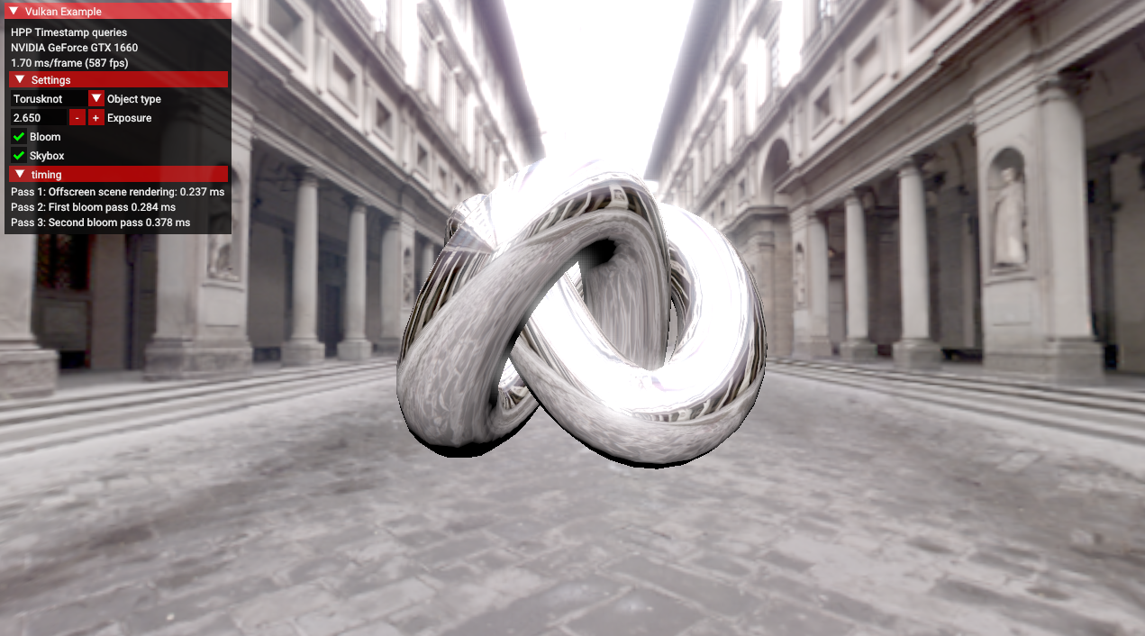
timestamp_queries
-
 .
.
-
Allows changing the object, toggling the skybox, changing the exposure, toggling bloom.
-
-
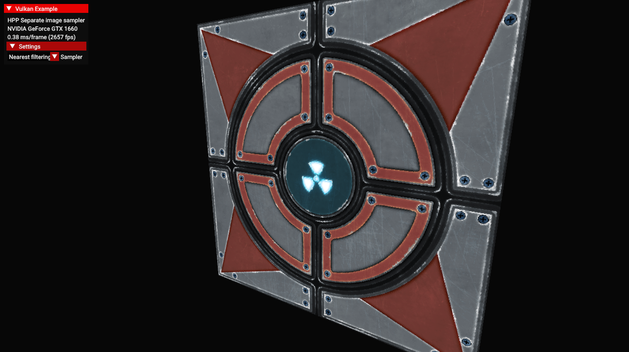
separate_image_sampler
-
 .
.
-
Allows selecting linear or nearest filtering.
-
-
texture_loading
-
 .
.
-
Allows increasing the LOD bias, reducing image quality.
-
-
texture_mipmap_generation
-
 .
.
-
Allows calibrating the LOD bias, and choosing between mipmap off, bilinear and anisotropic.
-
-
hello_triangle_1_3 / hello_triangle
-
 .
.
-
Nothing special
-
No dynamic resize.
-
Extensions
-
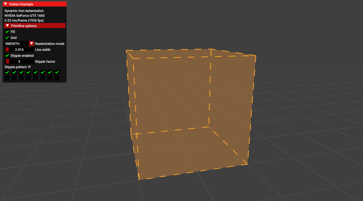
dynamic_line_rasterization
-
 .
.
-
This sample demonstrates functions from various extensions related to dynamic line rasterization.
-
These functions can be useful for developing CAD applications.
-
From the
EXT_line_rasterizationextension.-
vkCmdSetLineStippleEXT- sets the stipple pattern.
-
-
From the
EXT_extended_dynamic_state3extension:-
vkCmdSetPolygonModeEXT- sets how defined primitives should be rasterized. -
vkCmdSetLineRasterizationModeEXT- sets the algorithm for line rasterization. -
vkCmdSetLineStippleEnableEXT- toggles stippling for lines.
-
-
And also from core Vulkan:
-
vkCmdSetLineWidth- sets the line width. -
vkCmdSetPrimitiveTopologyEXT- defines which type of primitives is being drawn.
-
-
-
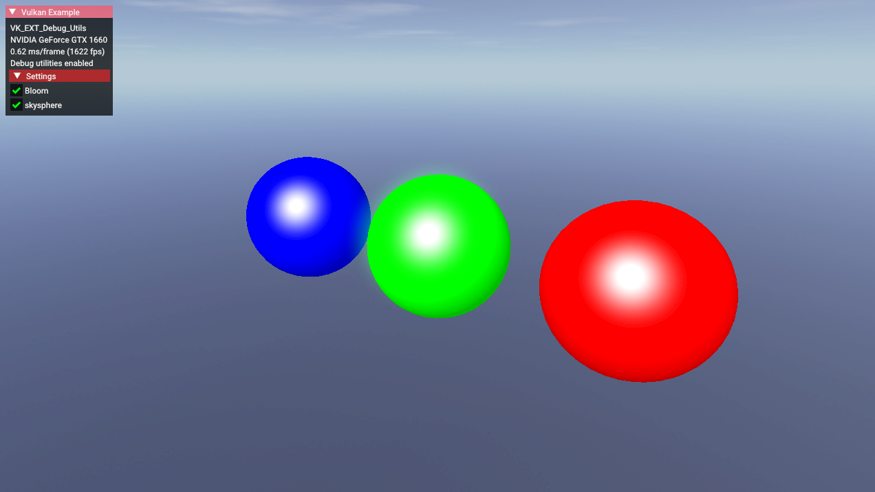
debug utils
-
 .
.
-
Toggle bloom, toggle skybox.
-
The
EXT_debug_utilsextension to setup a validation layer messenger callback and pass additional debugging information to debuggers like RenderDoc. -
EXT_debug_utilshas been introduced based on feedback for the initial Vulkan debugging extensionsEXT_debug_reportandEXT_debug_marker, combining these into a single instance extension with some added functionality. -
Procedure examples :
-
vkCmdBeginDebugUtilsLabelEXT -
vkCmdInsertDebugUtilsLabelEXT -
vkCmdEndDebugUtilsLabelEXT -
vkQueueBeginDebugUtilsLabelEXT -
vkQueueInsertDebugUtilsLabelEXT -
vkQueueEndDebugUtilsLabelEXT -
vkSetDebugUtilsObjectNameEXT -
vkSetDebugUtilsObjectTagEXT
-
-
-
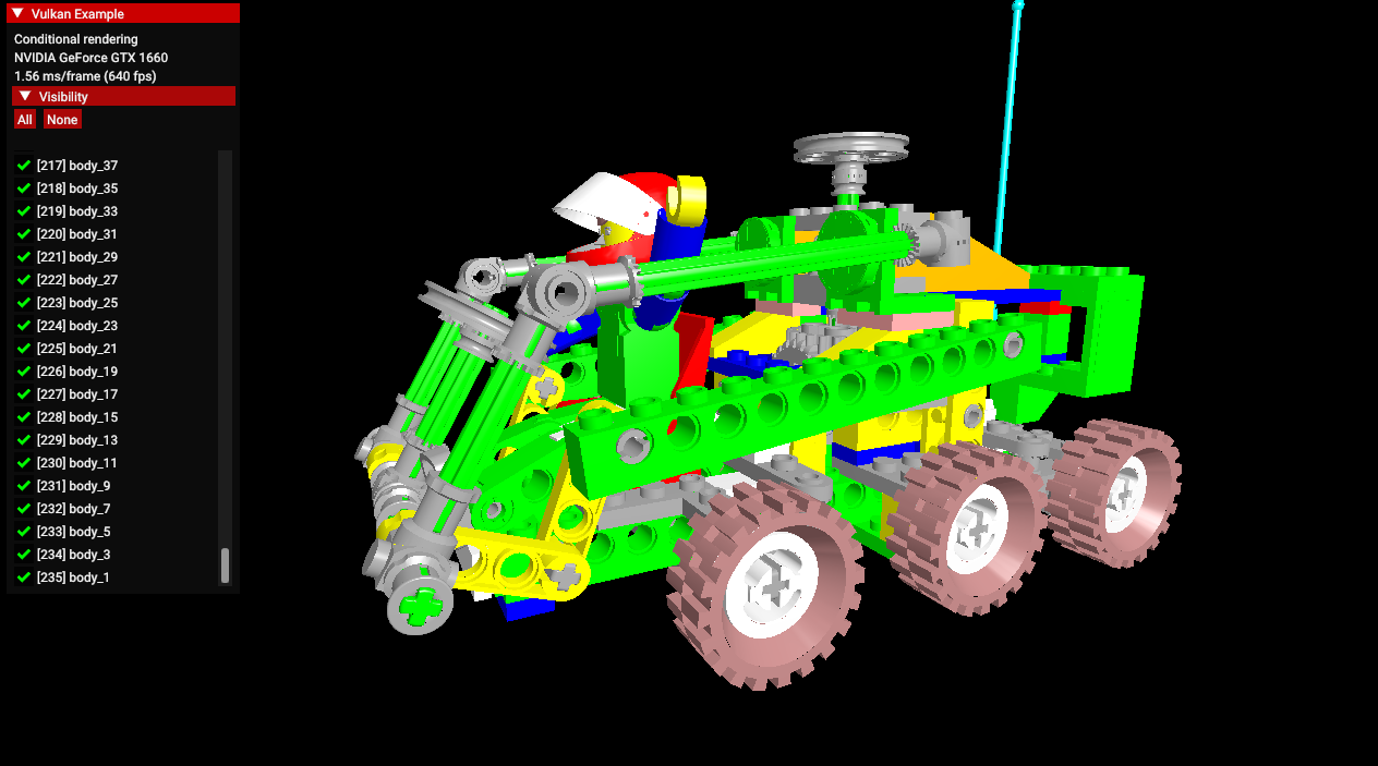
conditional_rendering
-
 .
.
-
A list of 235 parts of the car, which can be disabled to not render.
-
The
EXT_conditional_renderingextension allows the execution of rendering commands to be conditional based on a value taken from a dedicated conditional buffer. -
This may help an application reduce latency by conditionally discarding rendering commands without application intervention.
-
This sample demonstrates usage of this extension for conditionally toggling the visibility of sub-meshes of a complex glTF model.
-
Instead of having to update command buffers, this is done by updating the aforementioned buffer.
-
-
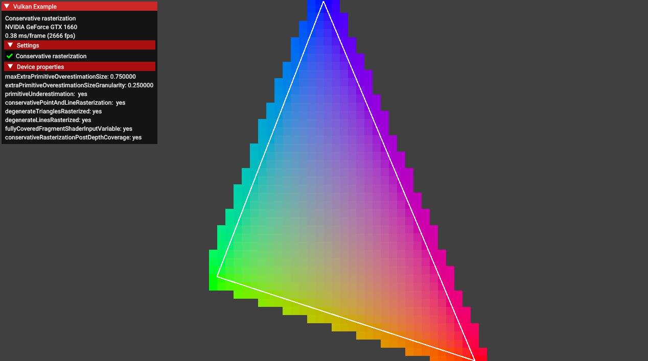
conservative_rasterization
-
 .
.
-
Enabling the conservative rasterization option causes this blending effect.
-
EXT_conservative_rasterizationchanges the way fragments are generated. -
Enables overestimation to generate fragments for every pixel touched instead of only pixels that are fully covered.
-
-
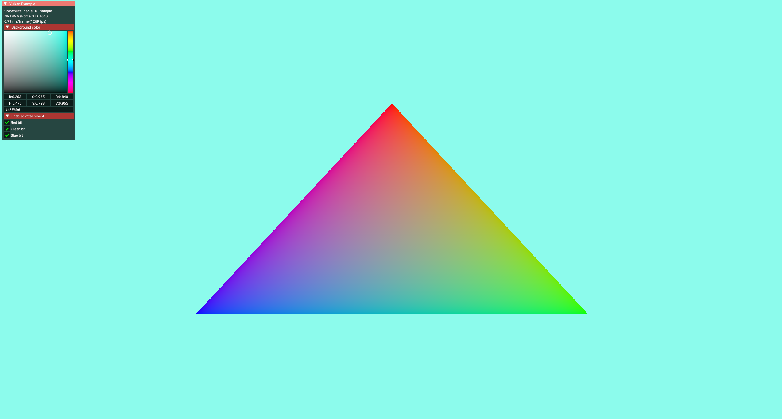
color_write_enable
-
 .
.
-
Color picker to change the background color.
-
Some options for "bit", changing the triangle color.
-
The
EXT_color_write_enableextension allows toggling the output color attachments using a pipeline dynamic state. -
It allows the program to prepare an additional framebuffer populated with the data from a defined color blend attachment which can be blended dynamically to the final scene.
-
The final results are comparable to those obtained with
vkCmdSetColorWriteMaskEXT, but it does not require the GPU driver to supportEXT_extended_dynamic_state3.
-
-
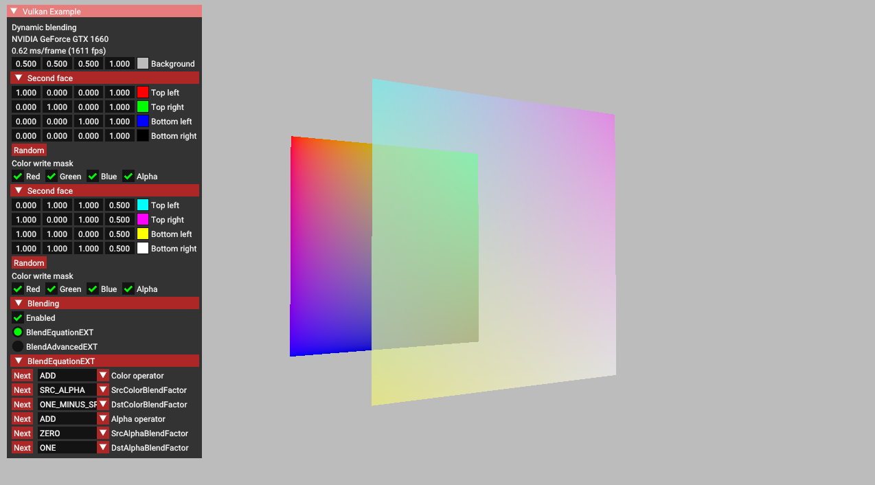
dynamic_blending
-
-
This sample demonstrates the functionality of
EXT_extended_dynamic_state3related to blending. -
It includes the following features:
-
vkCmdSetColorBlendEnableEXT: toggles blending on and off. -
vkCmdSetColorBlendEquationEXT: modifies blending operators and factors. -
vkCmdSetColorBlendAdvancedEXT: utilizes more complex blending operators. -
vkCmdSetColorWriteMaskEXT: toggles individual channels on and off.
-
-
-
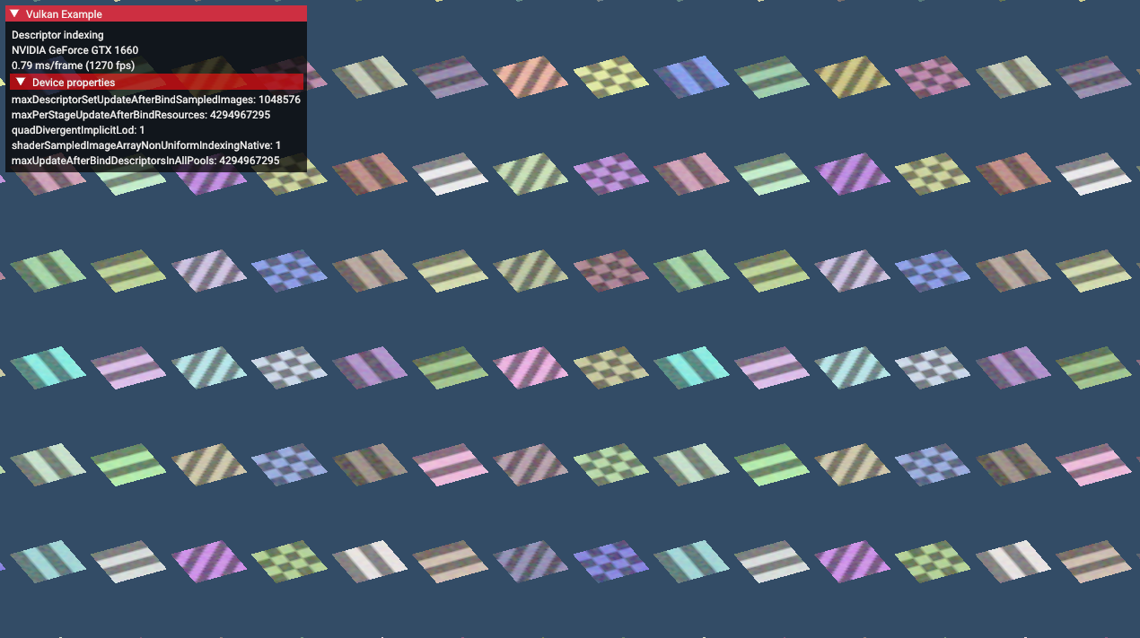
descriptor_indexing
-
 .
.
-
-
~descriptor_buffer_basic
-
 .
.
-
Just boxes rotating, I didn't understand.
-
Just textures rotating, I didn't understand.
-
-
dynamic_multisample_rasterization
-
This sample demonstrates one of the functionalities of
EXT_extended_dynamic_state3related to rasterization samples. -
The extension can be used to dynamically change sampling without the need to swap pipelines.
-
 .
.
-
This thing took quite a while to open, generating binary files, etc.
-
-
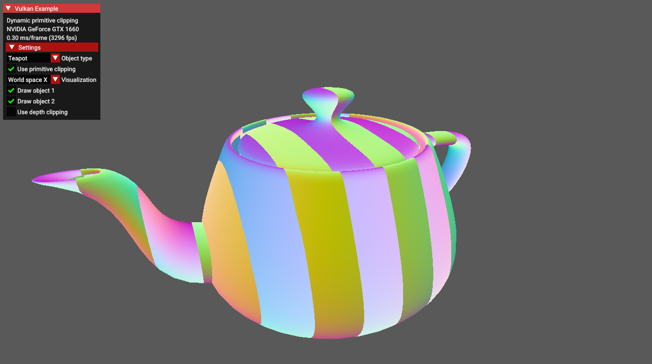
dynamic_primitive_clipping
-
 .
.
-
This sample demonstrates how to apply depth clipping using the
vkCmdSetDepthClipEnableEXT()command which is a part of theEXT_extended_dynamic_state3extension. -
Additionally it also shows how to apply primitive clipping using the
gl_ClipDistance[]builtin shader variable. -
It is worth noting that primitive clipping and depth clipping are two separate features of the fixed-function vertex post-processing stage.
-
They're both described in the same chapter of the Vulkan specification (chapter 27.4, "Primitive clipping").
-
What is primitive clipping
-
Primitives produced by vertex/geometry/tessellation shaders are sent to fixed-function vertex post-processing.
-
Primitive clipping is a part of post-processing pipeline in which primitives such as points/lines/triangles are culled against the cull volume and then clipped to the clip volume.
-
And then they might be further clipped by results stored in the
gl_ClipDistance[]array - values in this array must be calculated in a vertex/geometry/tessellation shader. -
In the past, the fixed-function version of the OpenGL API provided a method to specify parameters for up to 6 clipping planes (half-spaces) that could perform additional primitive clipping. Fixed-function hardware calculated proper distances to these planes and made a decision - should the primitive be clipped against these planes or not (for historical study - search for the
glClipPlane()description). -
Vulkan inherited the idea of primitive clipping, but with one important difference: the user has to calculate the distance to the clip planes on their own in the vertex shader.
-
And - because the user does it in a shader - they do not have to use clip planes at all. It can be any kind of calculation, as long as the results are put in the
gl_ClipDistance[]array. -
Values that are less than 0.0 cause the vertex to be clipped. In the case of a triangle primitive the whole triangle is clipped if all of its vertices have values stored in
gl_ClipDistance[]below 0.0. When some of these values are above 0.0 - the triangle is split into new triangles as described in the Vulkan specification.
-
-
What is depth clipping
-
When depth clipping is disabled then effectively there is no near or far plane clipping.
-
Depth values of primitives that are behind the far plane are clamped to the far plane depth value (usually 1.0).
-
Depth values of primitives that are in front of the near plane are clamped to the near plane depth value (by default it's 0.0, but may be set to -1.0 if we use settings defined in
VkPipelineViewportDepthClipControlCreateInfoEXTstructure. This requires the presence of theEXT_depth_clip_controlextension which is not part of this tutorial). -
In this sample the result of depth clipping (or lack of it) is not clearly visible at first. Try to move the viewer position closer to the object and see how the "use depth clipping" checkbox changes object appearance.
-
-
-
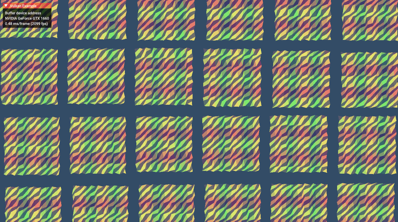
~buffer_device_address.
-
 .
.
-
I didn't understand. It's just things moving.
-
-
~calibrated_timestamps
-
timestamp_queries, but with other timings.
-
Core
Instance / Extensions
Instance
-
VkInstance-
The Vulkan context, used to access drivers.
-
-
The instance is the connection between your application and the Vulkan library.
-
-
Optional, but it may provide some useful information to the driver to optimize our specific application.
-
-
-
Tells the Vulkan driver which global extensions and validation layers we want to use.
-
Instance Level Extensions
-
vkEnumerateInstanceExtensionProperties()-
Retrieve a list of supported extensions before creating an instance.
-
Each
VkExtensionPropertiesstruct contains the name and version of an extension.
-
Debugging
Validation Layers
-
Layers .
-
Vulkan is designed for high performance and low driver overhead, therefore, it will include very limited error checking and debugging capabilities by default.
-
The driver will often crash instead of returning an error code if you do something wrong, or worse, it will appear to work on your graphics card and completely fail on others.
-
Vulkan allows you to enable extensive checks through a feature known as validation layers .
-
Validation layers are pieces of code that can be inserted between the API and the graphics driver to do things like running extra checks on function parameters and tracking memory management problems.
-
The nice thing is that you can enable them during development and then completely disable them when releasing your application for zero overhead. Anyone can write their own validation layers, but the Vulkan SDK by LunarG provides a standard set of validation layers. You also need to register a callback function to receive debug messages from the layers.
-
Because Vulkan is so explicit about every operation and the validation layers are so extensive, it can actually be a lot easier to find out why your screen is black compared to OpenGL and Direct3D!
-
Common operations in validation layers are:
-
Checking the values of parameters against the specification to detect misuse
-
Tracking the creation and destruction of objects to find resource leaks
-
Checking thread safety by tracking the threads that calls originate from
-
Logging every call and its parameters to the standard output
-
Tracing Vulkan calls for profiling and replaying
-
-
There were formerly two different types of validation layers in Vulkan: instance and device specific.
-
The idea was that instance layers would only check calls related to global Vulkan objects like instances, and device-specific layers would only check calls related to a specific GPU.
-
Device-specific layers have now been deprecated , which means that instance validation layers apply to all Vulkan calls.
-
We don’t really need to check for the existence of this extension because it should be implied by the availability of the validation layers.
-
vkEnumerateInstanceLayerProperties -
RenderDoc :
-
Do not run validation at the same time as RenderDoc, otherwise you'll also be validating RenderDoc.
-
-
Vulkan Configurator :
-
Overwrites the normal Layer setup.
-
Implicitly loads layers.
-
How to use :
-
RIGHT-CLICK.
-
-
-
Performance :
-
Ensure validation layers and debug callbacks are off for performance runs. Use pipeline cache objects to avoid repeated pipeline creation cost.
-
I notice how each 'push', 'descriptor set bind', 'vertex bind', 'indices bind' and 'draw' were a lot slower with validations on.
-
Message Callback
-
The validation layers will print debug messages to the standard output by default, but we can also handle them ourselves by providing an explicit callback in our program.
-
This will also allow you to decide which kind of messages you would like to see.
-
messageSeverity -
messageType -
pfnUserCallback-
messageSeverity-
DEBUG_UTILS_MESSAGE_SEVERITY_VERBOSE_EXT-
Diagnostic message
-
-
DEBUG_UTILS_MESSAGE_SEVERITY_INFO_EXT-
Informational message like the creation of a resource
-
-
DEBUG_UTILS_MESSAGE_SEVERITY_WARNING_EXT-
Message about behavior that is not necessarily an error, but very likely a bug in your application
-
-
DEBUG_UTILS_MESSAGE_SEVERITY_ERROR_EXT-
Message about behavior that is invalid and may cause crashes.
-
-
-
messageType-
DEBUG_UTILS_MESSAGE_TYPE_GENERAL_EXT-
Some event has happened that is unrelated to the specification or performance
-
-
DEBUG_UTILS_MESSAGE_TYPE_VALIDATION_EXT-
Something has happened that violates the specification or indicates a possible mistake
-
-
DEBUG_UTILS_MESSAGE_TYPE_PERFORMANCE_EXT-
Potential non-optimal use of Vulkan
-
-
-
pCallbackData-
Refers to a
VkDebugUtilsMessengerCallbackDataEXTstruct containing the details of the message itself, with the most important members being: -
pMessage-
The debug message as a null-terminated string
-
-
pObjects-
Array of Vulkan object handles related to the message
-
-
objectCount-
Number of objects in the array
-
-
-
pUserData-
Contains a pointer specified during the setup of the callback and allows you to pass your own data to it.
-
-
Debug Utils (
VK_EXT_debug_utils
)
must(
    vk.SetDebugUtilsObjectNameEXT(
        dev,
        &vk.DebugUtilsObjectNameInfoEXT {
            sType = .DEBUG_UTILS_OBJECT_NAME_INFO_EXT,
            objectType = obj,
            objectHandle = handle,
            pObjectName = strings.clone_to_cstring(name, context.temp_allocator),
        },
    ),
)
Window / Surface / GLFW
Window
-
The Vulkan API itself is completely platform-agnostic, which is why we need to use the standardized WSI (Window System Interface) extension to interact with the window manager.
-
Windows can be created with the native platform APIs or libraries like GLFW and SDL .
-
Some platforms allow you to render directly to a display without interacting with any window manager through the
KHR_displayandKHR_display_swapchainextensions. -
These allow you to create a surface that represents the entire screen and could be used to implement your own window manager, for example.
GLFW
-
The very first call in
initWindowshould beglfwInit(), which initializes the GLFW library. Because GLFW was originally designed to create an OpenGL context, we need to tell it to not create an OpenGL context with a later call: -
Because handling resized windows takes special care that we’ll look into later, disable it for now with another window hint call:
glfwWindowHint(GLFW_CLIENT_API, GLFW_NO_API);
glfwWindowHint(GLFW_RESIZABLE, GLFW_FALSE);
-
All that’s left now is creating the actual window. Add a
GLFWwindow* window;private class member to store a reference to it and initialize the window with:
window = glfwCreateWindow(WIDTH, HEIGHT, "Vulkan", nullptr, nullptr);
-
The first three parameters specify the width, height and title of the window. The fourth parameter allows you to optionally specify a monitor to open the window on, and the last parameter is only relevant to OpenGL.
-
Init:
void initWindow() {
    glfwInit();

    glfwWindowHint(GLFW_CLIENT_API, GLFW_NO_API);
    glfwWindowHint(GLFW_RESIZABLE, GLFW_FALSE);

    window = glfwCreateWindow(WIDTH, HEIGHT, "Vulkan", nullptr, nullptr);
}
-
Main loop:
void mainLoop() {
    while (!glfwWindowShouldClose(window)) {
        glfwPollEvents();
    }
}
-
Destroy:
void cleanup() {
    glfwDestroyWindow(window);

    glfwTerminate();
}
-
Blocking the Thread :
Surface
-
A
VkSurfaceKHRis an opaque handle representing a platform-specific presentation target (for example, a window on Windows, an X11 window on Linux, or a UIView on iOS). It is created directly from the Vulkan instance together with a native window handle. Conceptually, a surface is:-
Instance-level: it lives above any physical or logical device.
-
Window abstraction: it wraps the OS window or drawable so that Vulkan knows where to submit images for display.
-
Device-agnostic: you can create a surface before choosing which GPU you will use.
-
-
Once created, the surface is used by a chosen physical device to query presentation support, formats and capabilities, and then by the logical device to build a Swapchain.
-
A surface itself is not intrinsically tied to any particular physical or logical device, because:
-
Creation: you call
vkCreateSurfaceKHR(instance, …)without involving aVkPhysicalDeviceorVkDevicehandle. -
Lifetime: it exists even before you pick or create a device, and you destroy it with
vkDestroySurfaceKHR(instance, surface, …).
-
-
Lifetime :
-
The surface is tied to the GLFW window's lifecycle.
-
It does not change when the window is resized, minimized, or restored.
-
The same surface handle remains valid until you destroy it (e.g., when closing the window).
-
-
"Window surfaces are part of the larger topic of render targets and presentation".
Extensions
-
To establish the connection between Vulkan and the window system to present results to the screen, we need to use the WSI (Window System Integration) extensions.
-
The
KHR_surfaceexposes aVkSurfaceKHRobject that represents an abstract type of surface to present rendered images to. -
The surface in our program will be backed by the window that we’ve already opened with GLFW.
-
The
KHR_surfaceextension is an instance level extension, and we’ve actually already enabled it, because it’s included in the list returned byglfwGetRequiredInstanceExtensions. The list also includes some other WSI extensions that we’ll use in the next couple of chapters. -
The window surface needs to be created right after the instance creation, because it can actually influence the physical device selection.
-
It should also be noted that window surfaces are an entirely optional component in Vulkan if you just need off-screen rendering.
-
Vulkan allows you to do that without hacks like creating an invisible window (necessary for OpenGL).
-
-
Vulkan also allows you to remotely render from a non-presenting GPU or remotely over the internet, or run compute acceleration for AI without a render or presentation target.
-
Although the
VkSurfaceKHRobject and its usage is platform-agnostic, its creation isn’t because it depends on window system details. For example, it needs theHWNDandHMODULEhandles on Windows. Therefore, there is a platform-specific addition to the extension, which on Windows is calledKHR_win32_surfaceand is also automatically included in the list fromglfwGetRequiredInstanceExtensions. -
GLFW actually has
glfwCreateWindowSurfacethat handles the platform differences for us.
Blocking the thread
-
A callback
glfw.SetWindowRefreshCallbackallows the swapchain to be recreated while resizing.-
See [[#Swapchain Recreation]].
-
Physical Device / Logical Device
Physical Device
-
VkPhysicalDevice -
A GPU. Used to query physical GPU details, like features, capabilities, memory size, etc.
Device Level Extensions
Queue Families
-
Most operations performed with Vulkan, like draw commands and memory operations, are asynchronously executed by submitting them to a
VkQueue. -
Queues are allocated from queue families, where each queue family supports a specific set of operations in its queues.
-
For example, there could be separate queue families for graphics, compute and memory transfer operations.
-
-
The availability of queue families could also be used as a distinguishing factor in physical device selection.
-
It is possible for a device with Vulkan support to not offer any graphics functionality; however, all graphics cards with Vulkan support today will generally support all queue operations that we’re interested in.
-
-
We need to check which queue families are supported by the device and which one of these supports the commands that we want to use.
Presentation support
-
Although the Vulkan implementation may support window system integration, that does not mean that every device in the system supports it. Therefore, we need to extend
createLogicalDeviceto ensure that a device can present images to the surface we created. -
Since the presentation is a queue-specific feature, the problem is actually about finding a queue family that supports presenting to the surface we created.
-
It’s actually possible that the queue families supporting drawing commands and the queue families supporting presentation do not overlap.
-
It’s very likely that these end up being the same queue family after all, but throughout the program we will treat them as if they were separate queues for a uniform approach.
-
Nevertheless, you could add logic to explicitly prefer a physical device that supports drawing and presentation in the same queue for improved performance.
-
-
Therefore, we have to take into account that there could be a distinct presentation queue.
-
We’ll look for a queue family that has the capability of presenting to our window surface. The function to check for that is
vkGetPhysicalDeviceSurfaceSupportKHR, which takes the physical device, queue family index and surface as parameters. -
It should be noted that the availability of a presentation queue, as we checked in the previous chapter, implies that the Swapchain extension must be supported. However, the extension does have to be explicitly enabled.
-
Not all graphics cards are capable of presenting images directly to a screen for various reasons, for example, because they are designed for servers and don’t have any display outputs. Secondly, since image presentation is heavily tied into the window system and the surfaces associated with windows, it is not part of the Vulkan core. You have to enable the
KHR_swapchaindevice extension after querying for its support.
Surface Capabilities
-
The extents can change when resizing and you should requery the surface properties. Note that if it says the current extent is
{UINT32_MAX, UINT32_MAX}(happens on some platforms) then you'll need to ask the windowing system for an appropriate new size (but I don't know GLFW well enough to know ifGetFramebufferSizeis the right function for that purpose)
Logical Device
-
VkDevice -
The “logical” GPU context that you actually execute things on.
-
Where you describe more specifically which VkPhysicalDeviceFeatures you will be using, like multi viewport rendering and 64-bit floats.
-
You also need to specify which queue families you would like to use.
Queues
-
Queues .
-
VkQueue-
Execution “port” for commands.
-
GPUs will have a set of queues with different properties.
-
Some allow only graphics commands, others only allow memory commands, etc.
-
-
Command buffers are executed by submitting them into a queue, which will copy the rendering commands onto the GPU for execution.
-
-
The queues are automatically created along with the logical device, but we don’t have a handle to interface with them yet.
-
Device queues are implicitly cleaned up when the device is destroyed.
-
We can use the
vkGetDeviceQueuefunction to retrieve queue handles for each queue family. The parameters are the logical device, queue family, queue index and a pointer to the variable to store the queue handle in. Because we’re only creating a single queue from this family, we’ll simply use index0. -
Vulkan Guide:
-
It is common to see engines using 3 queue families:
-
One for drawing the frame, other for async compute, and other for data transfer.
-
-
In this tutorial, we use a single queue that will run all our commands for simplicity.
-
Multi-queue
-
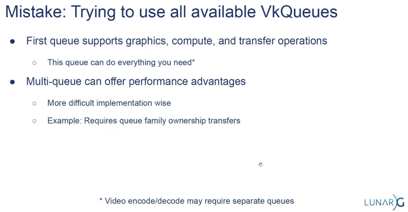 .
.
-
Some hardware only has one queue.
Render Loop
-
Now that everything is ready for rendering, you first ask the
VkSwapchainKHRfor an image to render to. Then you allocate aVkCommandBufferfrom aVkCommandBufferPoolor reuse an already allocated command buffer that has finished execution, and “start” the command buffer, which allows you to write commands into it. -
Next, you begin rendering by using Dynamic Rendering.
-
Then create a loop where you bind a
VkPipeline, bind someVkDescriptorSetresources (for the shader parameters), bind the vertex buffers, and then execute a draw call. -
If there is nothing more to render, you end the
VkCommandBuffer. Finally, you submit the command buffer into the queue for rendering. This will begin execution of the commands in the command buffer on the gpu. If you want to display the result of the rendering, you “present” the image you have rendered to to the screen. Because the execution may not have finished yet, you use a semaphore to make the presentation of the image to the screen wait until rendering is finished. -
At a high level, rendering a frame in Vulkan consists of a common set of steps:
-
Wait for the previous frame to finish
-
Acquire an image from the Swapchain
-
Record a command buffer which draws the scene onto that image
-
Re-recording every frame doesn't really take up performance.
-
-
Submit the recorded command buffer
-
Takes performance.
-
-
Present the Swapchain image
-
Puts it up on the screen.
-
-
Swapchain
-
Vulkan does not have the concept of a "default framebuffer," hence it requires an infrastructure that will own the buffers we will render to before we visualize them on the screen.
-
This infrastructure is known as the swapchain and must be created explicitly in Vulkan.
-
The Swapchain is essentially a queue of images that are waiting to be presented to the screen.
-
Our application will acquire such an image to draw to it, and then return it to the queue.
-
The conditions for presenting an image from the queue depend on how the Swapchain is set up.
-
The general purpose of the Swapchain is to synchronize the presentation of images with the refresh rate of the screen.
-
This is important to make sure that only complete images are shown.
-
-
Every time we want to draw a frame, we have to ask the Swapchain to provide us with an image to render to. When we’ve finished drawing a frame, the image is returned to the Swapchain for it to be presented to the screen at some point.
-
"Is a collection of render targets".
-
Render Targets is not a well-defined term.
-
-
The number of render targets and conditions for presenting finished images to the screen depends on the present mode.
-
VkSwapchainKHR-
Holds the images for the screen.
-
It allows you to render things into a visible window.
-
The
KHRsuffix shows that it comes from an extension, which in this case isKHR_swapchain.
-
-
-
Good video.
-
Pre-rotate on mobile.
-
When to recreate, recreation problems, recreation strategies, maintenance.
-
Present modes.
-
-
Support :
-
There are basically three kinds of properties we need to check:
-
Basic surface capabilities (min/max number of images in Swapchain, min/max width and height of images)
-
Surface formats (pixel format, color space)
-
Available presentation modes
-
-
It is important that we only try to query for Swapchain support after verifying that the extension is available.
-
Swapchain Creation
-
-
surface-
Is the surface onto which the swapchain will present images. If the creation succeeds, the swapchain becomes associated with
surface.
-
-
minImageCount-
we also have to decide how many images we would like to have in the Swapchain. However, simply sticking to the minimum means that we may sometimes have to wait on the driver to complete internal operations before we can acquire another image to render to. Therefore, it is recommended to request at least one more image than the minimum:
uint32_t imageCount = surfaceCapabilities.minImageCount + 1;-
We should also make sure to not exceed the maximum number of images while doing this, where
0is a special value that means that there is no maximum
if (surfaceCapabilities.maxImageCount > 0 && imageCount > surfaceCapabilities.maxImageCount) { imageCount = surfaceCapabilities.maxImageCount; } -
-
imageFormat-
For the color space we’ll use SRGB if it is available, because it results in more accurate perceived colors . It is also pretty much the standard color space for images, like the textures we’ll use later on.
-
Because of that we should also use an SRGB color format, of which one of the most common ones is
FORMAT_B8G8R8A8_SRGB.
-
-
imageColorSpace-
Is a VkColorSpaceKHR value specifying the way the swapchain interprets image data.
-
-
imageExtent-
Is the size (in pixels) of the swapchain image(s).
-
The swap extent is the resolution of the Swapchain images. It’s almost always exactly equal to the resolution of the window that we’re drawing to in pixels .
-
The range of the possible resolutions is defined in the
VkSurfaceCapabilitiesKHRstructure. -
On some platforms, it is normal that
maxImageExtentmay become(0, 0), for example when the window is minimized. In such a case, it is not possible to create a swapchain due to the Valid Usage requirements , unless scaling is selected through VkSwapchainPresentScalingCreateInfoKHR , if supported . -
We’ll pick the resolution that best matches the window within the
minImageExtentandmaxImageExtentbounds. But we must specify the resolution in the correct unit. -
GLFW uses two units when measuring sizes: pixels and screen coordinates . For example, the resolution
{WIDTH, HEIGHT}that we specified earlier when creating the window is measured in screen coordinates. But Vulkan works with pixels, so the Swapchain extent must be specified in pixels as well. -
Unfortunately, if you are using a high DPI display (like Apple’s Retina display), screen coordinates don’t correspond to pixels. Instead, due to the higher pixel density, the resolution of the window in pixel will be larger than the resolution in screen coordinates. So if Vulkan doesn’t fix the swap extent for us, we can’t just use the original
{WIDTH, HEIGHT}. Instead, we must useglfwGetFramebufferSizeto query the resolution of the window in pixel before matching it against the minimum and maximum image extent. -
The surface capabilities changes every time the window resizes, and it's only used for creating the Swapchain, so it doesn't make sense to cache.
-
-
imageUsage -
imageSharingMode(Handling multiple queues):-
We need to specify how to handle Swapchain images that will be used across multiple queue families. That will be the case in our application if the graphics queue family is different from the presentation queue. We’ll be drawing on the images in the Swapchain from the graphics queue and then submitting them on the presentation queue. There are two ways to handle images that are accessed from multiple queues:
-
SHARING_MODE_EXCLUSIVE:-
An image is owned by one queue family at a time, and ownership must be explicitly transferred before using it in another queue family.
-
This option offers the best performance.
-
-
SHARING_MODE_CONCURRENT:-
Images can be used across multiple queue families without explicit ownership transfers.
-
Concurrent mode requires you to specify in advance between which queue families ownership will be shared using the
queueFamilyIndexCountandpQueueFamilyIndicesparameters.
-
-
-
If the queue families differ, then we’ll be using the concurrent mode in this tutorial to avoid having to do the ownership chapters, because these involve some concepts that are better explained at a later time.
-
If the graphics queue family and presentation queue family are the same, which will be the case on most hardware, then we should stick to exclusive mode. Concurrent mode requires you to specify at least two distinct queue families.
-
-
queueFamilyIndexCount-
Is the number of queue families having access to the image(s) of the swapchain when
imageSharingModeisSHARING_MODE_CONCURRENT.
-
-
pQueueFamilyIndices-
Is a pointer to an array of queue family indices having access to the images(s) of the swapchain when
imageSharingModeisSHARING_MODE_CONCURRENT.
-
-
imageArrayLayers-
Is the number of views in a multiview/stereo surface. For non-stereoscopic-3D applications, this value is 1.
-
-
presentMode -
preTransform-
We can specify that a certain transform should be applied to images in the Swapchain if it is supported (
supportedTransformsincapabilities), like a 90-degree clockwise rotation or horizontal flip. To specify that you do not want any transformation, simply specify the current transformation. -
IDENTITY-
This would not be optimal on devices that support rotation and will lead to measurable performance loss.
-
It is strongly recommended that
surface_properties.currentTransformbe used instead. However, the application is required to handlepreTransformelsewhere accordingly.
-
-
-
compositeAlpha-
Specifies if the alpha channel should be used for blending with other windows in the window system.
-
You’ll almost always want to simply ignore the alpha channel, hence
OPAQUE.
-
-
clipped-
If set to
TRUE, then that means that we don’t care about the color of pixels that are obscured, for example, because another window is in front of them. -
Unless you really need to be able to read these pixels back and get predictable results, you’ll get the best performance by enabling clipping.
-
-
oldSwapChain-
Can be an existing non-retired swapchain currently associated with
surface, orNULL_HANDLE. -
If the
oldSwapchainisNULL_HANDLE:-
And if the native window referred to by
pCreateInfo->surfaceis already associated with a Vulkan swapchain,ERROR_NATIVE_WINDOW_IN_USEmust be returned.
-
-
If the
oldSwapchainis valid:-
This may aid in the resource reuse, and also allows the application to still present any images that are already acquired from it.
-
And the
oldSwapchainhas exclusive full-screen access, that access is released frompCreateInfo->oldSwapchain. If the command succeeds in this case, the newly created swapchain will automatically acquire exclusive full-screen access frompCreateInfo->oldSwapchain. -
And there are outstanding calls to
vkWaitForPresent2KHR, thenvkCreateSwapchainKHRmay block until those calls complete. -
Any images from
oldSwapchainthat are not acquired by the application may be freed by the implementation, upon callingvkCreateSwapchainKHR, which may occur even if creation of the new swapchain fails. -
The
oldSwapchainwill be retired upon callingvkCreateSwapchainKHR, even if creation of the new swapchain fails.-
After
oldSwapchainis retired, the application can pass tovkQueuePresentKHRany images it had already acquired fromoldSwapchain.-
An application may present an image from the old swapchain before an image from the new swapchain is ready to be presented.
-
As usual,
vkQueuePresentKHRmay fail ifoldSwapchainhas entered a state that causesERROR_OUT_OF_DATEto be returned.
-
-
-
The application can continue to use a shared presentable image obtained from
oldSwapchainuntil a presentable image is acquired from the new swapchain, as long as it has not entered a state that causes it to returnERROR_OUT_OF_DATE. -
The application can destroy
oldSwapchainto free all memory associated witholdSwapchain.
-
-
Regardless if the
oldSwapchainis valid or not:-
The new swapchain is created in the non-retired state.
-
-
-
flags-
Is a bitmask of
VkSwapchainCreateFlagBitsKHRindicating parameters of the swapchain creation. -
SWAPCHAIN_CREATE_DEFERRED_MEMORY_ALLOCATION_EXT-
When
EXT_swapchain_maintenance1is available, you can optionally amortize the cost of swapchain image allocations over multiple frames. -
When this is used, image views cannot be created until the first time the image is acquired.
-
The idea is that normally the images and image views are acquired when a Swapchain recreation happens, but if this flag is enabled it is necessary to acquire them after
result == SUCCESS || result == SUBOPTIMAL_KHRas the result ofvkAcquireNextImageKHR.
-
-
-
-
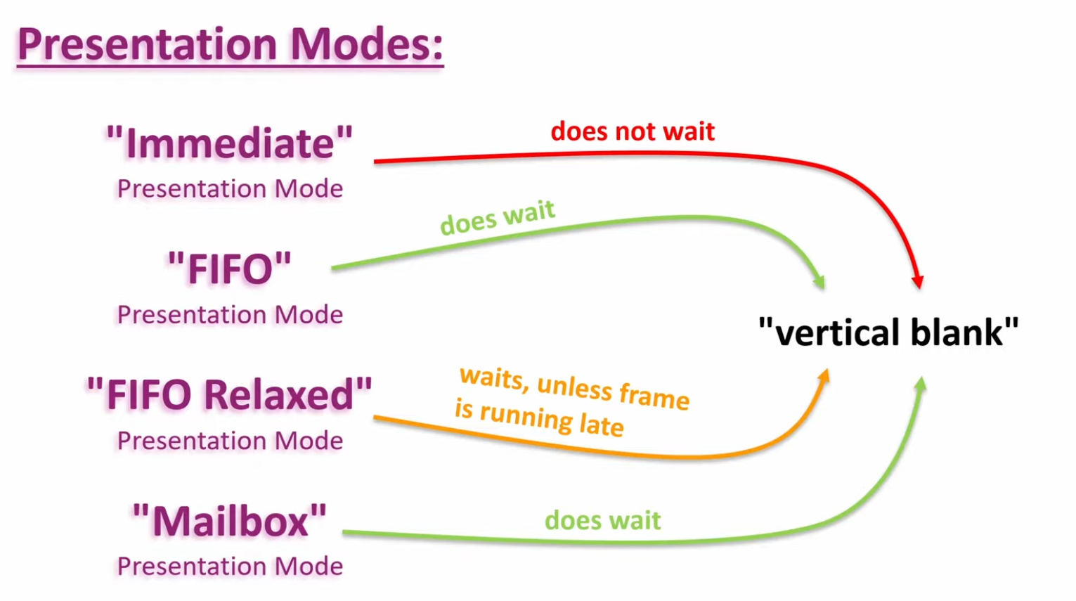
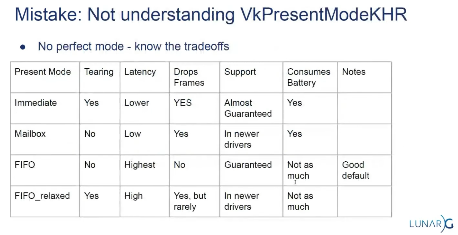
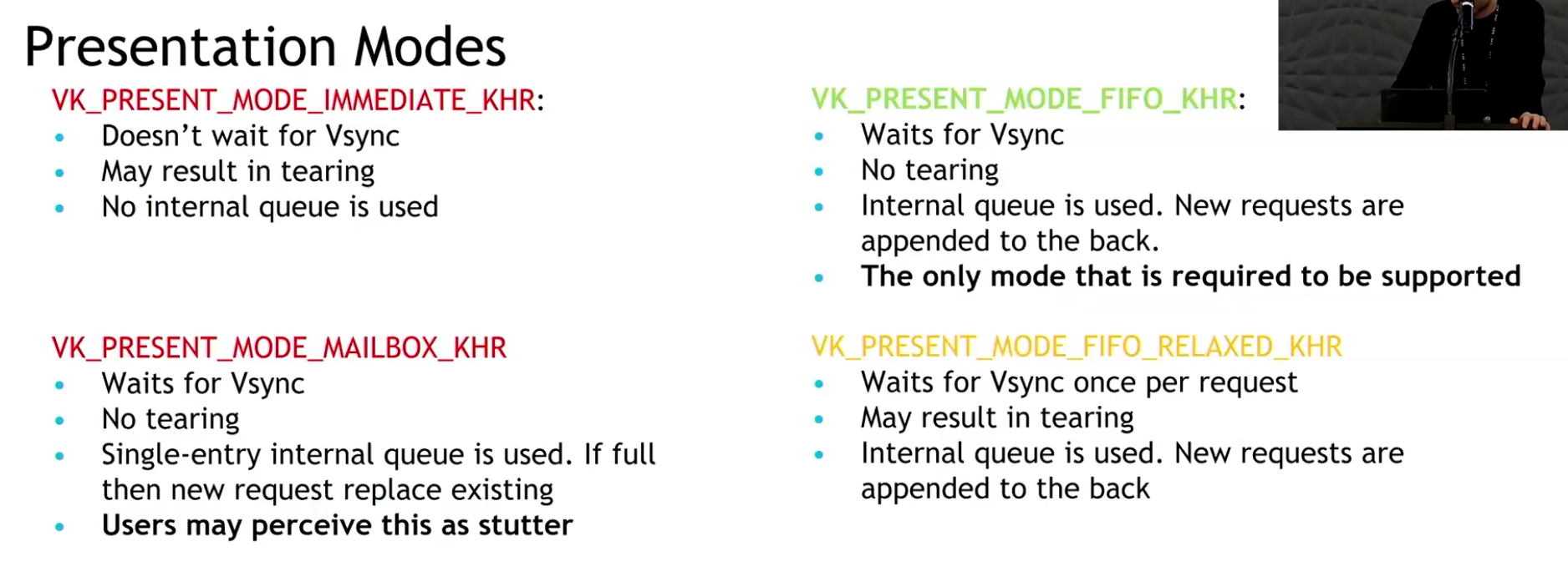
Present Modes
-
Common present modes are double buffering (vsync) and triple buffering.
-
The presentation mode is arguably the most important setting for the Swapchain, because it represents the actual conditions for showing images to the screen. There are four possible modes available in Vulkan:
-
PRESENT_MODE_IMMEDIATE_KHR-
Images submitted by your application are transferred to the screen right away, which may result in tearing.
-
-
PRESENT_MODE_FIFO_KHR-
The Swapchain is a queue where the display takes an image from the front of the queue when the display is refreshed, and the program inserts rendered images at the back of the queue. If the queue is full, then the program has to wait. This is most similar to vertical sync as found in modern games. The moment that the display is refreshed is known as "vertical blank".
-
-
PRESENT_MODE_FIFO_RELAXED_KHR-
This mode only differs from the previous one if the application is late and the queue was empty at the last vertical blank. Instead of waiting for the next vertical blank, the image is transferred right away when it finally arrives. This may result in visible tearing.
-
-
PRESENT_MODE_MAILBOX_KHR-
This is another variation of the second mode. Instead of blocking the application when the queue is full, the images that are already queued are simply replaced with the newer ones. This mode can be used to render frames as fast as possible while still avoiding tearing, resulting in fewer latency issues than standard vertical sync. This is commonly known as "triple buffering," although the existence of three buffers alone does not necessarily mean that the framerate is unlocked.
-
-
-
Only the
PRESENT_MODE_FIFO_KHRmode is guaranteed to be available, so we’ll again have to write a function that looks for the best mode that is available: -
 .
.
-
Options :
-
I think that
PRESENT_MODE_MAILBOX_KHRis a very nice trade-off if energy usage is not a concern. It allows us to avoid tearing while still maintaining fairly low latency by rendering new images that are as up to date as possible right until the vertical blank. -
On mobile devices, where energy usage is more important, you will probably want to use
PRESENT_MODE_FIFO_KHRinstead. -
 .
.
-
 .
.
-
Slide from the Samsung talk on (2025-02-25).
-
It recommends FIFO and says that mailbox is not as good as it seems because it induces a lot of stutter.
-
-
Drawing directly to the Swapchain vs Blitting to the Swapchain
-
Source .
-
Drawing directly into the swapchain :
-
Is fine for many projects, and it can even be optimal in some cases such as phones.
-
Restrictions :
-
Their resolution is fixed to whatever your window size is.
-
If you want to have higher or lower resolution, and then do some scaling logic, you need to draw into a different image.
-
Swapchain image size (imageExtent / surface extent) is part of swapchain creation and is tied to the surface. If you want an internal render at a different resolution (supersampling, dynamic resolution, lower-res upscaling), you create an offscreen image/render-target at the desired size and then copy/blit/resolve/tone-map into the swapchain image for presentation. The spec and WSI notes treat imageExtent as the surface-presentable size.
-
-
The formats of the image used in the swapchain are not guaranteed.
-
Different OS, drivers, and windowing modes can have different optimal swapchain formats.
-
The WSI model exposes the surface’s supported formats to the application via
vkGetPhysicalDeviceSurfaceFormatsKHR(or equivalent WSI queries); the returned list is implementation- and surface-dependent, so you must choose from what the platform/driver exposes. That means formats available for swapchains vary by OS, driver, and surface. -
Vulkan explicitly states this via
VkSurfaceFormatKHRandvkGetPhysicalDeviceSurfaceFormatsKHR. The specification (Section 30.5 "WSI Swapchain", Vulkan 1.3.275) and tutorials emphasize that the application must query and choose from available formats supported by the surface/device combination. Android documentation (Vulkan on Android) and Windows (DXGI_FORMAT) similarly highlight platform-specific format requirements and HDR needs (e.g.,FORMAT_A2B10G10R10_UNORM_PACK32orDXGI_FORMAT_R10G10B10A2_UNORMfor HDR10). This variability makes direct rendering inflexible.
-
-
HDR support needs its own very specific formats.
-
HDR output requires specific color formats and color-space metadata (examples: 10-bit packed UNORM formats or explicit HDR color-space support such as ST2084/Perceptual Quantizer). WSI and sample repos treat HDR as a distinct case (e.g. A2B10G10 formats and HDR color spaces). Support is platform- and driver-dependent.
-
-
Swapchain formats are, for the most part, low precision.
-
Some platforms with High Dynamic Range rendering have higher precision formats, but you will often default to 8 bits per color.
-
So if you want high precision light calculations, systems that would prevent banding, or to be able to go past 1.0 on the normalized color range, you will need a separate image for drawing.
-
HDR/high-dynamic-range lighting typically uses floating-point or extended-range render targets (e.g.
R16G16B16A16_SFLOATor higher) for intermediate lighting accumulation; final tonemapping reduces values into the presentable format. Because presentable swapchain images are often limited (8-bit), the offscreen high-precision image plus a conversion/tonemap pass is the usual pattern.
-
-
Many surfaces expose 8-bit UNORM or sRGB formats (e.g.
B8G8R8A8_UNORM/SRGB) as commonly returned swapchain formats. Higher-precision formats (16-bit float per channel or 10-bit packed) exist and are used for HDR/high-precision pipelines, but they are not guaranteed by every surface/driver. Therefore applications that need high-precision lighting/accumulation commonly render into a 16-bit-float render target and tonemap/convert for presentation. -
Banding artifacts in gradients or low-light scenes are a well-known consequence of limited precision. High-precision rendering (HDR, complex lighting, deferred shading G-Buffers) requires formats like
FORMAT_R16G16B16A16_SFLOAT(RGBA16F) to store values outside the [0.0, 1.0] range and prevent banding. While some swapchains can support HDR formats (e.g., 10:10:10:2), they are less universally available and not the default. Using RGBA16F directly in a swapchain is often unsupported or inefficient for presentation.
-
-
-
-
Drawing to a different image and copying/blitting to the swapchain image :
-
Advantages :
-
Decouples tonemapping from presentation timing
-
Tonemap into an intermediate LDR image that you control. You can finish the tonemap pass earlier and defer the actual transfer/present of the swapchain image to a later point, reducing risk of stalling the present path or blocking on swapchain ownership.
-
-
Avoids writing directly to the swapchain
-
Writing directly into the swapchain can introduce stalls (wait-for-acquire or present-time synchronization). Using an intermediate LDR image lets you do the heavy work off-swapchain and only do a cheap transfer/present step when convenient.
-
-
Enables batching / chaining of postprocesses without touching the swapchain
-
If you need further LDR processing (dithering, temporal AA, UI composite, overlays, readback for screenshots, or additional filters), do those against the intermediate image. This allows composing multiple passes without repeatedly transitioning the swapchain.
-
-
Easier support for multiple outputs or different sizes/formats
-
You can tonemap once to an LDR image and then blit/copy to different-size or different-format targets (screenshots, streaming encoder, secondary displays) without re-running tonemap.
-
-
Allows use of transient/optimized memory for the intermediate
-
The intermediate image can be created as transient (e.g.,
MEMORY_PROPERTY_LAZILY_ALLOCATEDor tiled transient attachment) to reduce memory pressure and bandwidth compared with always keeping a full persistent LDR buffer.
-
-
Better control over final conversion semantics
-
In shader you control quantization, gamma conversion, ordered/temporal dithering, and color-space tagging. After producing the controlled LDR image you can choose the transfer method (exact copy vs scaled blit) that matches target capabilities, improving visual consistency across vendors.
-
-
Improved cross-queue / async workflows
-
You can produce the LDR image on a graphics/compute queue and then perform a transfer on a transfer-only queue (or use a dedicated present queue) with explicit ownership transfers, possibly improving throughput if hardware supports it.
-
-
Facilitates deterministic screenshots / capture
-
Saving an intermediate LDR image for file export is safer (format/bit-depth known) than capturing the swapchain which may have platform-specific transforms applied.
-
-
-
Trade-offs :
-
Extra GPU memory usage
-
You need memory for the intermediate LDR image (unless you use transient attachments), which increases resident memory footprint.
-
-
Extra GPU bandwidth and a copy step
-
Creating an LDR image then copying/blitting to the swapchain costs memory bandwidth and GPU cycles. This can increase frame time if the transfer is on the critical path.
-
-
More layout transitions and synchronization complexity
-
You must manage transitions and possibly ownership transfers (if different queues are used). Incorrect synchronization can cause stalls or correctness bugs.
-
-
Potential increased latency if done poorly
-
If the copy/blit is done synchronously right before present, it can add latency compared with rendering directly to the swapchain; the intended decoupling only helps if scheduling is arranged to avoid the critical path.
-
-
Implementation complexity
-
Managing an extra render target, transient allocation, and copy logic is more code than rendering directly to the swapchain.
-
-
-
Swapchain Recreation
When to recreate
-
If the window surface changed such that the Swapchain is no longer compatible with it.
-
If the window resizes.
-
If the window minimizes.
-
This case is special because it will result in a framebuffer size of
0. -
We can handle by waiting for the framebuffer size to be back to something greater than
0, indicating that the window is no longer minimized.
-
-
If the swapchain image format changed during an application's lifetime, for example, when moving a window from a standard range to a high dynamic range monitor.
Finding out that a recreation is needed
-
The
vkAcquireNextImageKHRandvkQueuePresentKHRfunctions can return the following special values to indicate this.-
ERROR_OUT_OF_DATE_KHR-
The Swapchain has become incompatible with the surface and can no longer be used for rendering. Usually happens after a window resize.
-
-
SUBOPTIMAL_KHR-
The Swapchain can still be used to successfully present to the surface, but the surface properties are no longer matched exactly.
-
You should ALWAYS recreate the swapchain if the result is suboptimal.
-
This result means that it's a "success" but there will be performance penalties.
-
Both
SUCCESSandSUBOPTIMAL_KHRare considered "success" return codes.
-
-
-
If the Swapchain turns out to be out of date when attempting to acquire an image, then it is no longer possible to present to it. Therefore, we should immediately recreate the Swapchain and try again in the next
drawFramecall. -
You could also decide to do that if the Swapchain is suboptimal, but I’ve chosen to proceed anyway in that case because we’ve already acquired an image.
result = presentQueue.presentKHR( presentInfoKHR );
if (result == vk::Result::eErrorOutOfDateKHR || result == vk::Result::eSuboptimalKHR) {
    framebufferResized = false;
    recreateSwapChain();
} else if (result != vk::Result::eSuccess) {
    throw std::runtime_error("failed to present Swapchain image!");
}

currentFrame = (currentFrame + 1) % MAX_FRAMES_IN_FLIGHT;
-
The
vkQueuePresentKHRfunction returns the same values with the same meaning. In this case, we will also recreate the Swapchain if it is suboptimal, because we want the best possible result. -
Finding out explicitly :
-
Although many drivers and platforms trigger
ERROR_OUT_OF_DATE_KHRautomatically after a window resize, it is not guaranteed to happen. -
That’s why we’ll add some extra code to also handle resizes explicitly:
glfw.SetWindowUserPointer(vulkan_context.glfw_window, vulkan_context) glfw.SetFramebufferSizeCallback(vulkan_context.glfw_window, proc "c" (window: glfw.WindowHandle, _, _: i32) {s vulkan_context := cast(^Vulkan_Context)glfw.GetWindowUserPointer(window) vulkan_context.glfw_framebuffer_resized = true }) -
"Usually it's not the best idea to depend on this".
-
Problems with multithreading.
-
You depend on the windowing system to notify changes correctly; this can be really tricky on mobile.
-
-
Recreating
void recreateSwapChain() {
    device.waitIdle();

    cleanupSwapChain();

    createSwapChain();
    createImageViews();
}
-
Synchronization :
-
~Flush and Recreate:
-
"We first call
vkDeviceWaitIdle, because just like in the last chapter, we shouldn’t touch resources that may still be in use."-
This is not enough.
-
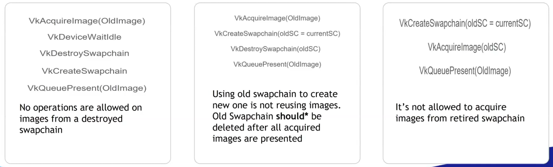 .
.
-
-
The whole app has to stop and wait for synchronization.
-
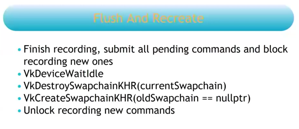 .
.
-
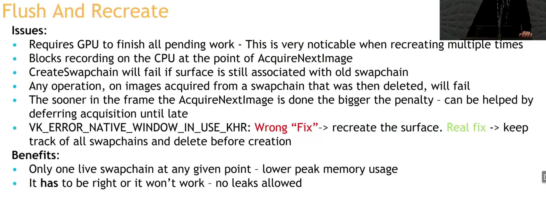 .
.
-
-
Recreate and check:
-
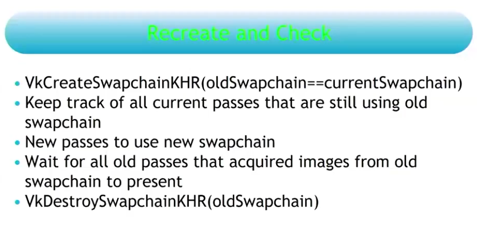 .
.
-
You do not need to stop your rendering at any given point.
-
The reason why you are allowed to pass the old swapchain when recreating the new swapchain, is due to this strategy.
-
This is the recommendation.
-
Strategy .
-
This issue is resolved by deferring the destruction of the old swapchain and its remaining present semaphores to the time when the semaphore corresponding to the first present of the new swapchain can be destroyed. Because once the first present semaphore of the new swapchain can be destroyed, the first present operation of the new swapchain is done, which means the old swapchain is no longer being presented.
-
The destruction of both old swapchains must now be deferred to when the first QP of the new swapchain has been processed. If an application resizes the window constantly and at a high rate, we would keep accumulating old swapchains and not free them until it stops.
-
This potentially accumulates a lot of memory, I think.
-
-
So what's the correct moment then? Only after the new swapchain has completed one full cycle of presentations, that is, when I acquire image index
0for the second time.
-
-
Analysis :
-
(2025-08-19)
-
Holy, now I understand the problem.
-
I cannot delete anything from the old swapchain until I am sure that everything from the previous one has been presented. I thought that by acquiring the first image of the new swapchain, that would already indicate that it was safe to delete the old swapchain, but that's not true; by doing that, I only guarantee that 1 (ONE) image from the old swapchain has been presented, but the old swapchain may have several images in the queue.
-
However, as made clear, that is not the case.
-
Dealing with this can be a nightmare. Potentially having to handle multiple old swapchains at the same time in case of very frequent resizes (smooth swapchain).
-
-
-
-
"You should always use this extension if available".
-
Support :
-
Introduced in 2023.
-
(2025-02-25)
-
Only 25% of Android devices and 20% of desktop GPUs use it.
-
It was added on Android 14.
-
-
-
Adds a collection of window system integration features that were intentionally left out or overlooked in the original
KHR_swapchainextension. -
Features :
-
Allow applications to release previously acquired images without presenting them.
-
Allow applications to defer swapchain memory allocation for improved startup time and memory footprint.
-
Specify a fence that will be signaled when the resources associated with a present operation can be safely destroyed.
-
Allow changing the present mode a swapchain is using at per-present granularity.
-
Allow applications to define the behavior when presenting a swapchain image to a surface with different dimensions than the image.
-
Using this feature may allow implementations to avoid returning
ERROR_OUT_OF_DATE_KHRin this situation.
-
-
This extension makes
vkQueuePresentKHRmore similar tovkQueueSubmit, allowing it to specify a fence that the application can wait on.
-
-
The problem with
vkDeviceWaitIdleorvkQueueWaitIdle:-
Typically, applications call these functions and assume it’s safe to delete swapchain semaphores and the swapchain itself.
-
The problem is that
WaitIdlefunctions are defined in terms of fences - they only wait for workloads submitted through functions that accept a fence. -
Unextended
vkQueuePresentdoes not provide a fence parameter. -
The
vkDeviceWaitIdlecan’t guarantee that it’s safe to delete swapchain resources.-
The validation layers don't trigger errors in this case, but it's just because so many people use it and there's no good alternative.
-
When
EXT_swapchain_maintenance1is enabled the validation layer will report an error if the application shutdown sequence relies onvkDeviceWaitIdleorvkQueueWaitIdleto release swapchain resources instead of using a presentation fence.
-
-
The extension fixes this problem.
-
By waiting on the presentation fence, the application can safely release swapchain resources.
-
-
-
To avoid a deadlock, only reset the fence if we are submitting work:
-
If reset is made right after wait for the fence, but the window was resized, then it will happen a deadlock.
-
The fence is opened by the signaling of
QueueSubmit, and closed by theResetFences.
vkWaitForFences(device, 1, &inFlightFences[currentFrame], TRUE, UINT64_MAX); uint32_t imageIndex; VkResult result = vkAcquireNextImageKHR(device, swapChain, UINT64_MAX, imageAvailableSemaphores[currentFrame], NULL_HANDLE, &imageIndex); if (result == ERROR_OUT_OF_DATE_KHR) { recreateSwapChain(); return; } else if (result != SUCCESS && result != SUBOPTIMAL_KHR) { throw std::runtime_error("failed to acquire Swapchain image!"); } // Only reset the fence if we are submitting work vkResetFences(device, 1, &inFlightFences[currentFrame]); -
-
-
What to recreate :
-
The image views need to be recreated because they are based directly on the Swapchain images.
-
-
Smooth Swapchain Resizing :
-
"Don't bother with smooth swapchain resizing, it's not worth it".
-
My experience :
-
(2025-08-04)
-
A callback
glfw.SetWindowRefreshCallbackallows the swapchain to be recreated while resizing. -
Synchronization :
-
Since the swapchain is recreated all the time, it becomes difficult to manage when the old swapchain should be destroyed along with its resources.
-
At the moment I'm handling the old_swapchain in a "bad" way, and I feel that recreating it every resize frame only worsens synchronization.-
It is not necessary to deal with the old_swapchain when using
vkDeviceWaitIdle().
-
-
-
My current implementation:
eng.window_init(1280, 720, "Expedicao Hover", proc "c" (window: glfw.WindowHandle) {
    context = eng.global_context
    // fmt.printfln("REFRESHED")
    eng.swapchain_resize()
    game_draw(&game, game.cycle_draw.dt_cycles_s)
})
-
-
Updating resources after recreating
-
Destroy every image and view created from the old swapchain (the swapchain destroys its own images).
-
Update everything that holds a reference to either of those.
-
If anything was created using the swapchain's size you also have to destroy and recreate those and update anything that references them.
-
There's no getting around it.
-
Frames In-Flight
Motivation
-
The render loop has one glaring flaw: unnecessary idling of the host. We are required to wait on the previous frame to finish before we can start rendering the next.
-
To fix this we allow multiple frames to be in-flight at once, allowing the rendering of one frame to not interfere with the recording of the next.
-
This control over the number of frames in flight is another example of Vulkan being explicit.
Frame
-
There is no concept of a frame in Vulkan. This means that the way you render is entirely up to you. The only thing that matters is when you have to display the frame to the screen, which is done through a swapchain. But there is no fundamental difference between rendering and then sending the images over the network, or saving the images into a file, or displaying it on the screen through the swapchain.
-
This means it is possible to use Vulkan in an entirely headless mode, where nothing is displayed to the screen. You can render the images and then store them on disk (very useful for testing) or use Vulkan as a way to perform GPU calculations such as a raytracer or other compute tasks.
How many Frames In-Flight
-
We choose the number 2 because we don’t want the CPU to get too far ahead of the GPU.
-
With two frames in flight, the CPU and the GPU can be working on their own tasks at the same time. If the CPU finishes early, it will wait till the GPU finishes rendering before submitting more work.
-
With three or more frames in flight, the CPU could get ahead of the GPU, adding frames of latency. Generally, extra latency isn’t desired.
-
One Per Frame In-Flight
-
Duplicate :
-
Resources :
-
Uniform Buffers.
-
If modified while a previous frame uses it, corruption occurs.
-
-
Dynamic Storage Buffers.
-
GPU-computed results (e.g., particle positions). Writing to a buffer while an older frame reads it causes hazards.
-
-
Color/Depth Attachments.
-
Staging Buffers
-
If updated per frame (e.g.,
vkMapMemory), duplication avoids overwriting mid-transfer.
-
-
Compute Shader Output Buffers:
-
If frame
Nwrites, and frameN+1reads, duplicate to prevent read-before-write. -
Use ping-pong buffers (count = frames in-flight).
-
-
-
Command pool.
-
I have doubts about this; some people do it differently.
-
-
Command buffer.
-
'present_finished_semaphore'.
-
'render_finished_fence'.
-
-
Don't duplicate :
-
Resources :
-
Static Vertex/Index Buffers:
-
Initialized once, read-only. No per-frame updates.
-
-
Immutable Textures
-
Loaded once (e.g., via
VkDeviceMemory). -
Not mapped for change.
-
It's device local.
-
-
-
Static BRDF LUTs.
-
Initialized once, read by all frames.
-
-
Advancing a frame
void drawFrame() {
    ...

    currentFrame = (currentFrame + 1) % MAX_FRAMES_IN_FLIGHT;
}
-
By using the modulo (
%) operator, we ensure that the frame index loops around after everyMAX_FRAMES_IN_FLIGHTenqueued frames.
Acquire Next Image
-
vkWaitForFences()-
Waits on the previous frame.
-
Takes an array of fences and waits on the host for either any or all of the fences to be signaled before returning.
-
The
TRUEwe pass here indicates that we want to wait for all fences, but in the case of a single one it doesn’t matter. -
This function also has a timeout parameter that we set to the maximum value of a 64 bit unsigned integer,
UINT64_MAX, which effectively disables the timeout.
-
-
vkAcquireNextImageKHR()-
Acquire the index of an available image from the swapchain for rendering .
-
If an image was acquired, then it means that this image is idle (i.e., not currently being displayed or written to).
-
If no image is ready, the call blocks (or returns an error if non-blocking).
-
The returned image index is now " owned " by your app for rendering.
-
We only get a swapchain image index from the windowing present system.
-
A semaphore/fence is signaled when the image is safe to use.
-
timeout-
If the swapchain doesn’t have any image we can use, it will block the thread with a maximum for the timeout set.
-
The measurement unit is nanoseconds.
-
1 second is fine:
1_000_000_000.
-
-
semaphore-
Semaphore to signal.
-
-
fence-
Fence to signal.
-
It is possible to specify a semaphore, fence or both.
-
-
pImageIndex-
Specifies a variable to output the index of the Swapchain image that has become available to use.
-
The index refers to the
VkImagein theswapChainImagesarray.
-
-
Image Layout Transitions
-
See Vulkan#Images .
-
Before we can start rendering to an image, we need to transition its layout to one that is suitable for rendering.
-
Before rendering, we transition the image layout to
IMAGE_LAYOUT_COLOR_ATTACHMENT_OPTIMAL.
// Before starting rendering, transition the swapchain image to COLOR_ATTACHMENT_OPTIMAL
transition_image_layout(
    imageIndex,
    vk::ImageLayout::eUndefined,
    vk::ImageLayout::eColorAttachmentOptimal,
    {},                                                     // srcAccessMask (no need to wait for previous operations)
    vk::AccessFlagBits2::eColorAttachmentWrite,                // dstAccessMask
    vk::PipelineStageFlagBits2::eTopOfPipe,                   // srcStage
    vk::PipelineStageFlagBits2::eColorAttachmentOutput        // dstStage
);
-
After rendering, we need to transition the image layout back to
IMAGE_LAYOUT_PRESENT_SRC_KHRso it can be presented to the screen:
// After rendering, transition the swapchain image to PRESENT_SRC
transition_image_layout(
    imageIndex,
    vk::ImageLayout::eColorAttachmentOptimal,
    vk::ImageLayout::ePresentSrcKHR,
    vk::AccessFlagBits2::eColorAttachmentWrite,                 // srcAccessMask
    {},                                                      // dstAccessMask
    vk::PipelineStageFlagBits2::eColorAttachmentOutput,        // srcStage
    vk::PipelineStageFlagBits2::eBottomOfPipe                  // dstStage
);
Render Targets
Attachments
-
Nvidia: Use
storeOp = DONT_CARErather thanUNDEFINEDlayouts to skip unneeded render target writes. -
Nvidia: Don't transition color attachments from "safe" to "unsafe" unless required by the algorithm.
Transient Resources
-
Transient attachments (or Transient Resources) are render targets (like color/depth buffers) designed to exist only temporarily during a render pass, with their contents discarded afterward. They're optimized for fast on-chip memory access and avoid unnecessary memory operations.
Render Target
-
A Render Target is not a term in Vulkan but it's a term in graphics programming.
-
It's a term for an image you render into. In Vulkan this is an
VkImage+VkImageViewused as a color/depth attachment in a render pass or as a color attachment in dynamic rendering. -
Examples :
-
Vulkan#Drawing to a High Precision Image (
R16G16B16A16_SFLOAT) .-
It's a Render Target technique to draw into a high-precision image and then copy the result to an SDR image for the swapchain.
-
-
-
Drawing a UI :
-
The UI texture must preserve alpha in the areas you want to be transparent, for later compositing.
-
Draw UI directly to the final render target (swapchain image, or image to blit to the swapchain image) :
-
After tonemap, enable blending and draw UI.
-
Oni:
-
For the scene, I render into an RGBA16 image, then I draw on the swapchain with a tonemapper, then I draw the UI on the swapchain with blending enabled.
-
-
-
Composite in a shader :
-
Sample scene image and UI image, compute
out = scene * (1 - alpha_ui) + ui * alpha_ui(or use premultiplied alpha:out = scene + ui).-
Both ways work; premultiplied alpha avoids some edge artifacts if UI already uses premultiplied data.
-
-
-
-
Compositing :
-
Used to combine render targets, or any other images.
-
Fragment shader :
-
Render to an image and draw a full-screen triangle/quad that samples the HDR image and outputs LDR color.
-
Could be the swapchain image if supported, or an intermediate image then blit/copy to swapchain.
-
-
Pros :
-
Simple and guaranteed compatible with swapchain color attachment usage.
-
Useful if you want to draw the UI while making this final composition.
-
Seems like I'm mixing responsibilities, even though I'm reducing one render pass.
-
-
-
Cons :
-
Less flexible for arbitrary per-pixel work that requires many conditionals or random write patterns.
-
Need to issue a draw call and set up graphics pipeline.
-
-
-
Compute shader :
-
Sample HDR image(s), write the LDR pixels to an output image.
-
Could be the swapchain image if supported, or an intermediate image then blit/copy to swapchain.
-
-
Pros :
-
Flexible: can read multiple inputs and write arbitrary outputs (random writes, multiple passes) without needing geometry.
-
Easy to implement multi-image compositing in one dispatch (read N sampled images + write to storage image).
-
-
Cons :
-
On some GPUs a simple full-screen fragment pass can be faster due to fixed-function hardware for rasterization and blending.
-
#version 450

layout(local_size_x = 16, local_size_y = 16) in;
layout(set=0, binding=0) uniform sampler2D gameTex;
layout(set=0, binding=1) uniform sampler2D uiTex;
layout(set=0, binding=2, rgba8) uniform writeonly image2D swapchainImg;

void main() {
    ivec2 coord = ivec2(gl_GlobalInvocationID.xy);
    vec2 uv = vec2(coord) / textureSize(gameTex, 0);

    // Sample inputs
    vec3 game = texture(gameTex, uv).rgb;
    vec4 ui = texture(uiTex, uv);

    // Tonemap game (example: Reinhard)
    game = game / (game + vec3(1.0));

    // Composite: UI over game
    vec3 final = mix(game, ui.rgb, ui.a);

    // Write to swapchain
    imageStore(swapchainImg, coord, vec4(final, 1.0));
}
#version 450 layout(local_size_x = 16, local_size_y = 16) in; layout(binding = 0) uniform sampler2D uSceneHDR; layout(binding = 1) uniform sampler2D uUI; // optional layout(binding = 2, rgba8) writeonly uniform image2D outImage; // target LDR image (could be swapchain-compatible image) vec3 reinhardTonemap(vec3 c) { return c / (1.0 + c); } vec3 toSRGB(vec3 linear) { return pow(linear, vec3(1.0/2.2)); } void main() { ivec2 pix = ivec2(gl_GlobalInvocationID.xy); ivec2 size = imageSize(outImage); if (pix.x >= size.x || pix.y >= size.y) return; vec2 uv = (vec2(pix) + 0.5) / vec2(size); vec3 hdr = texture(uSceneHDR, uv).rgb; float exposure = 1.0; vec3 mapped = reinhardTonemap(hdr * exposure); mapped = toSRGB(mapped); // Optionally composite UI // vec4 ui = texture(uUI, uv); // vec3 outc = mix(mapped, ui.rgb, ui.a); imageStore(outImage, pix, vec4(mapped, 1.0)); }// Dispatch vkCmdBindPipeline(cmd, PIPELINE_BIND_POINT_COMPUTE, computePipe); vkCmdBindDescriptorSets(cmd, PIPELINE_BIND_POINT_COMPUTE, ...); vkCmdDispatch(cmd, swapchain_width/16, swapchain_height/16, 1); -
-
Dynamic Rendering
-
Support :
-
Dynamic Rendering Local Read .
-
Used for tiling GPUs.
-
-
Dynamic Rendering Unused Attachments .
-
Requires Vulkan 1.3+.
-
Proposal .
-
VkPhysicalDeviceDynamicRenderingUnusedAttachmentsFeaturesEXT .
-
It relaxes the strict matching rules so a rendering instance and the bound pipelines may disagree about an attachment being “unused” in one but not the other (and relaxes some format/NULL mixing rules described in the extension).
-
Support :
-
Pass VkPhysicalDeviceDynamicRenderingUnusedAttachmentsFeaturesEXT in the
pNextchain of the VkPhysicalDeviceFeatures2 structure passed to vkGetPhysicalDeviceFeatures2 . -
The struct will be filled in to indicate whether each corresponding feature is supported.
-
-
Enabling :
-
Enable the corresponding feature in
VkDeviceCreateInfo(viaVkPhysicalDeviceDynamicRenderingUnusedAttachmentsFeaturesEXT)
-
-
This extension lifts some restrictions in the KHR_dynamic_rendering extension to allow render pass instances and bound pipelines within those render pass instances to have an unused attachment specified in one but not the other. It also allows pipelines to use different formats in a render pass as long as the attachment is NULL.
-
-
Structure specifying attachment information
-
imageView-
Is the image view that will be used for rendering.
-
-
imageLayout-
Is the layout that
imageViewwill be in during rendering.
-
-
resolveMode-
Is a VkResolveModeFlagBits value defining how data written to
imageViewwill be resolved intoresolveImageView.
-
-
resolveImageView-
Is an image view used to write resolved data at the end of rendering.
-
-
resolveImageLayout-
Is the layout that
resolveImageViewwill be in during rendering.
-
-
loadOp-
Specifies what to do with the image before rendering.
-
Is a VkAttachmentLoadOp value defining the load operation for the attachment.
-
We’re using
ATTACHMENT_LOAD_OP_CLEARto clear the image to black before rendering.
-
-
storeOp-
Specifies what to do with the image after rendering.
-
Is a VkAttachmentStoreOp value defining the store operation for the attachment.
-
We're using
ATTACHMENT_STORE_OP_STOREto store the rendered image for later use.
-
-
clearValue-
Is a VkClearValue structure defining values used to clear
imageViewwhenloadOpisATTACHMENT_LOAD_OP_CLEAR.
-
-
-
-
Structure specifying render pass instance begin info.
-
Specifies the attachments to render to and the render area.
-
Combines the
RenderingAttachmentInfowith other rendering parameters. -
flags-
Is a bitmask of VkRenderingFlagBits .
-
-
renderArea-
Is the render area that is affected by the render pass instance.
-
Extent Requirements :
-
The
rendering_info.renderArea.extenthas to fit inside therendering_attachment.imageViewand hence the image.
-
-
If there is an instance of VkDeviceGroupRenderPassBeginInfo included in the
pNextchain and itsdeviceRenderAreaCountmember is not0, thenrenderAreais ignored, and the render area is defined per-device by that structure. -
CharlesG - LunarG:
-
Viewports & scissors let you specify a size smaller than the full image, as well as redefining the origin & scale to use. Whereas the renderArea is specifying the actual image dimensions to use. This allows flexibility in how the backing VkImage is used in contrast to the viewport/scissor needs of the rendering itself. In most cases they are going to be “full” so its not like it comes into play always
-
More clarity: viewport & scissor are inputs to the rasterization stage, while the render area is an input for the attachment read/write.
-
-
Caio:
-
So, when comparing these two cases:
-
1- I use a 1080p image for the
renderAreaand a640pviewport and center the offset -
2- I use a 640p image for the
renderAreaand a640pviewport and center the offset
-
-
Is there a difference between the quality and performance of these two? Or even, is there a visual difference?
-
-
CharlesG - LunarG:
-
I don't know tbh.
-
-
-
colorAttachmentCount-
Is the number of elements in
pColorAttachments.
-
-
pColorAttachments-
Is a pointer to an array of
colorAttachmentCountVkRenderingAttachmentInfo structures describing any color attachments used. -
Each element of the
pColorAttachmentsarray corresponds to an output location in the shader, i.e. if the shader declares an output variable decorated with aLocationvalue of X , then it uses the attachment provided inpColorAttachments[X]. -
If the
imageViewmember of any element ofpColorAttachmentsis NULL_HANDLE , andresolveModeis notRESOLVE_MODE_EXTERNAL_FORMAT_DOWNSAMPLE_ANDROID, writes to the corresponding location by a fragment are discarded.
-
-
pDepthAttachment-
Is a pointer to a VkRenderingAttachmentInfo structure describing a depth attachment.
-
-
pStencilAttachment-
Is a pointer to a VkRenderingAttachmentInfo structure describing a stencil attachment.
-
-
viewMask-
Is a bitfield of view indices describing which views are active during rendering, when it is not
0.
-
-
layerCount-
Is the number of layers rendered to in each attachment when
viewMaskis0. -
Specifies the number of layers to render to, which is 1 for a non-layered image.
-
-
Multi-view
-
If
VkRenderingInfo.viewMaskis not0, multiview is enabled. -
If multiview is enabled, and the
multiviewPerViewRenderAreasfeature is enabled, and there is an instance of VkMultiviewPerViewRenderAreasRenderPassBeginInfoQCOM included in thepNextchain withperViewRenderAreaCountnot equal to0, then the elements of VkMultiviewPerViewRenderAreasRenderPassBeginInfoQCOM ::pPerViewRenderAreasoverriderenderAreaand define a render area for each view. In this case,renderAreamust be an area at least as large as the union of all the per-view render areas.
Render Cmds
Drawing Commands
Draw Direct
-
Specify the Viewport and Scissor.
-
Bind the pipeline.
-
Bind the descriptor sets.
-
vkCmdDraw()-
vertexCount-
Even though we don’t have a vertex buffer, we technically still have 3 vertices to draw.
-
-
instanceCount-
Used for instanced rendering, use
1if you’re not doing that.
-
-
firstVertex-
Used as an offset into the vertex buffer, defines the lowest value of
SV_VertexId.
-
-
firstInstance-
Used as an offset for instanced rendering, defines the lowest value of
SV_InstanceID.
-
-
-
-
indexCount-
The number of vertices to draw.
-
-
instanceCount-
The number of instances to draw.
-
We’re not using instancing, so just specify
1instance.
-
-
firstIndex-
The base index within the index buffer.
-
Specifies an offset into the index buffer, using a value of
1would cause the graphics card to start reading at the second index.
-
-
vertexOffset-
The value added to the vertex index before indexing into the vertex buffer.
-
-
firstInstance-
The instance ID of the first instance to draw.
-
-
Draw Indirect
-
"In some ways, Indirect Rendering is a more advanced form of instancing".
-
buffer + offset + (stride * index) -
Executing a draw-indirect call will be equivalent to doing this.
void FakeDrawIndirect(VkCommandBuffer commandBuffer,void* buffer,VkDeviceSize offset, uint32_t drawCount,uint32_t stride); char* memory = (char*)buffer + offset; for(int i = 0; i < drawCount; i++) { VkDrawIndexedIndirectCommand* command = VkDrawIndexedIndirectCommand*(memory + (i * stride)); VkCmdDrawIndexed(commandBuffer, command->indexCount, command->instanceCount, command->firstIndex, command->vertexOffset, command->firstInstance); } } -
It does not carry vertex data itself — it only supplies counts and base indices/instances. The actual vertex data and indices come from the buffers you previously bound with
vkCmdBindVertexBuffersandvkCmdBindIndexBuffer. -
Vertex :
-
To move vertex and index buffers to bindless, generally you do it by merging the meshes into really big buffers. Instead of having 1 buffer per vertex buffer and index buffer pair, you have 1 buffer for all vertex buffers in a scene. When rendering, then you use BaseVertex offsets in the drawcalls. In some engines, they remove vertex attributes from the pipelines entirely, and instead grab the vertex data from buffers in the vertex shader. Doing that makes it much easier to keep 1 big vertex buffer for all drawcalls in the engine even if they use different vertex attribute formats. It also allows some advanced unpacking/compression techniques, and it’s the main use case for Mesh Shaders.
-
We also change the way the meshes work. After loading a scene, we create a BIG vertex buffer, and stuff all of the meshes of the entire map into it. This way we will avoid having to rebind vertex buffers.
-
-
Implementation :
-
If the device supports multi-draw indirect (
VkPhysicalDeviceFeatures2::multiDrawIndirect), then the entire array of draw commands can be executed through a single call toVkDrawIndexedIndirectCommand. Otherwise, each draw call must be executed through a separate call toVkDrawIndexIndirectCommand:// m_enable_mci: supports multiDrawIndirect if (m_enable_mci && m_supports_mci) { vkCmdDrawIndexedIndirect(draw_cmd_buffers[i], indirect_call_buffer->get_handle(), 0, cpu_commands.size(), sizeof(cpu_commands[0])); } else { for (size_t j = 0; j < cpu_commands.size(); ++j) { vkCmdDrawIndexedIndirect(draw_cmd_buffers[i], indirect_call_buffer->get_handle(), j * sizeof(cpu_commands[0]), 1, sizeof(cpu_commands[0])); } } -
vkCmdDrawIndexedIndirectCount.-
Behaves similarly to vkCmdDrawIndexedIndirect except that the draw count is read by the device from a buffer during execution. The command will read an unsigned 32-bit integer from countBuffer located at countBufferOffset and use this as the draw count.
-
-
-
Textures :
-
Due to the fact that you want to have as much things on the GPU as possible, this pipeline maps very well if you combine it with “Bindless” techniques, where you stop needing to bind descriptor sets per material or changing vertex buffers. Having a bindless renderer also makes Raytracing much more performant and effective.
-
On this guide we will not use bindless textures as their support is limited, so we will do 1 draw-indirect call per material used.
-
To move textures into bindless, you use texture arrays.
-
With the correct extension, the size of the texture array can be unbounded in the shader, like when you use SSBOs.
-
Then, when accessing the textures in the shader, you access them by index which you grab from another buffer. If you don’t use the Descriptor Indexing extensions, you can still use texture arrays, but they will need a bounded size. Check your device limits to see how big can that be.
-
To make materials bindless, you need to stop having 1 pipeline per material. Instead, you want to move the material parameters into SSBOs, and go with an ubershader approach.
-
In the Doom engines, they have a very low amount of pipelines for the entire game. Doom eternal has less than 500 pipelines, while Unreal Engine games often have 100.000+ pipelines. If you use ubershaders to massively lower the amount of unique pipelines, you will be able to increase efficiency in a huge way, as VkCmdBindPipeline is one of the most expensive calls when drawing objects in vulkan.
-
-
Push Constants :
-
Push Constants and Dynamic Descriptors can be used, but they have to be “global”. Using push constants for things like camera location is perfectly fine, but you cant use them for object ID as that’s a per-object call and you specifically want to draw as many objects as possible in 1 draw.
-
Multithreading Rendering
-
I'm not sure, I don't think it's necessary.
-
From what I understand, it's about using multiple CPU threads to handle submissions and presentations, etc.
-
It has nothing to do with frames in flight, btw.
-
-
The video explains okay, but nah.
-
-> In the next video he says it wasn't exactly a good idea and reverted what he did in that video.
-
"It was technically slower and more confusing to do synchronizations".
-
-
Render Passes and Framebuffers
Dynamic Rendering: Features and differences from Render Passes
-
Replaces
VkRenderPassand Framebuffers.-
Instead, we can specify the color, depth, and stencil attachments directly when we begin rendering.
-
-
Describe renderpasses inline with command buffer recording.
-
Provides more flexibility by allowing us to change the attachments we’re rendering to without creating new render pass objects.
-
Greatly simplifies application architecture.
-
Synchronization still needs to be done, but now it's even more explicit, truer to its stated nature.
-
We had to do that with Render Passes, but that was bound up in the Render Pass creation.
-
Now, the synchronization is more explicit.
-
-
Tiling GPUs aren't left behind.
-
The v1.4
dynamicRenderingLocalRead,KHR_dynamic_rendering_local_readbrings tiling GPUs to the same capabilities, and they don't need to state the Render Passes.
-
-
I wouldn't say that "You should use Render Passes if your hardware isn't new enough", because it isn't fun.
-
Better compatibility with modern rendering techniques.
-
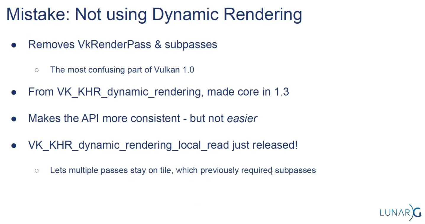 .
.
Subpasses
-
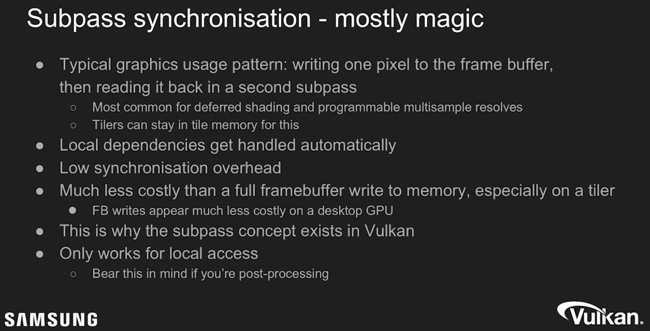 .
.
-
External subpass dependencies:-
Explained by TheMaister 2019; he is part of the Khronos Group.
-
The main purpose of external subpass dependencies is to deal with initialLayout and finalLayout of an attachment reference. If initialLayout != layout used in the first subpass, the render pass is forced to perform a layout transition.
-
If you don’t specify anything else, that layout transition will wait for nothing before it performs the transition. Or rather, the driver will inject a dummy subpass dependency for you with srcStageMask = TOP_OF_PIPE. This is not what you want since it’s almost certainly going to be a race condition. You can set up a subpass dependency with the appropriate srcStageMask and srcAccessMask.
-
The external subpass dependency is basically just a vkCmdPipelineBarrier injected for you by the driver.
-
The whole premise here is that it’s theoretically better to do it this way because the driver has more information, but this is questionable, at least on current hardware and drivers.
-
There is a very similar external subpass dependency setup for finalLayout. If finalLayout differs from the last use in a subpass, driver will transition into the final layout automatically. Here you get to change
dstStageMask/dstAccessMask. If you do nothing here, you getBOTTOM_OF_PIPE, which can actually be just fine. A prime use case here is swapchain images which havefinalLayout = PRESENT_SRC_KHR. -
Essentially, you can ignore external subpass dependencies .
-
Their added complexity gives very little gain. Render pass compatibility rules also imply that if you change even minor things like which stages to wait for, you need to create new pipelines!
-
This is dumb, and will hopefully be fixed at some point in the spec.
-
However, while the usefulness of external subpass dependencies is questionable, they have some convenient use cases I’d like to go over:
-
Automatically transitioning
TRANSIENT_ATTACHMENTimages :-
If you’re on mobile, you should be using transient images where possible. When using these attachments in a render pass, it makes sense to always have them as initialLayout = UNDEFINED. Since we know that these images can only ever be used in
COLOR_ATTACHMENT_OUTPUTorEARLY/LATE_FRAGMENT_TESTstages depending on their image format, the external subpass dependency writes itself, and we can just use transient attachments without having to think too hard about how to synchronize them. This is what I do in my Granite engine, and it’s quite useful. Of course, we could just inject a pipeline barrier for this exact same purpose, but that’s more boilerplate.
-
-
Automatically transitioning swapchain images :
-
Typically, swapchain images are always just used once per frame, and we can deal with all synchronization using external subpass dependencies. We want
initialLayout = UNDEFINED, andfinalLayout = PRESENT_SRC_KHR. -
srcStageMaskisCOLOR_ATTACHMENT_OUTPUTwhich lets us link up with the swapchain acquire semaphore. For this case, we will need an external subpass dependency. For thefinalLayouttransition after the render pass, we are fine withBOTTOM_OF_PIPEbeing used. We’re going to use semaphores here anyways. -
I also do this in Granite.
-
-
-
Framebuffers
-
VkFrameBuffer-
Holds the target images for a renderpass.
-
Only used in legacy tutorials.
-
-
Just wrappers to image views.
-
The attachments of a Framebuffer are the Image Views.
-
The Framebuffers are used within a Render Pass.
-
LunarG / Vulkan: "Kinda of a bad name, it's just a couple of image views".
-
Only exists to combine images and renderpasses.
Render Passes
-
VkRenderPass-
Holds information about the images you are rendering into. All drawing commands have to be done inside a renderpass.
-
Only used in legacy tutorials.
-
-
Render passes in Vulkan describe the type of images that are used during rendering operations, how they will be used, and how their contents should be treated.
-
All drawing commands happen inside a "render pass".
-
Acts as pseudo render graph.
-
Allows tiling GPUs to use memory efficiently.
-
Efficient scheduling.
-
-
Describe images attachments.
-
Defines the subpasses.
-
Declare dependencies between subpasses.
-
Require
VkFrameBuffers.-
Whereas a render pass only describes the type of images, a
VkFramebufferactually binds specific images to these slots.
-
-
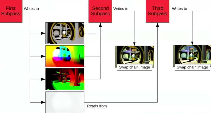 .
.
-
Problem :
-
Great in theory, not so great to use in practice.
-
Single object with many responsibilities.
-
Made the API harder to reason about when looking at the code.
-
-
Hard to architect into a renderer.
-
Yet another input for pipelines.
-
-
The main benefit is for tiling based GPUs.
-
Commonly found in mobile.
-
-
"Use Dynamic Rendering, it's much better".
-
Submit
-
Submits the Command Buffers recorded.
-
vkSubmitInfo-
The first three parameters specify which semaphores to wait on before execution begins and in which stage(s) of the pipeline to wait.
-
We want to wait for writing colors to the image until it’s available, so we’re specifying the stage of the graphics pipeline that writes to the color attachment.
-
That means that theoretically, the implementation can already start executing our vertex shader and such while the image is not yet available.
-
Each entry in the
waitStagesarray corresponds to the semaphore with the same index inpWaitSemaphores. -
pCommandBuffers-
Specifies which command buffers to actually submit for execution. We simply submit the single command buffer we have.
-
-
pSignalSemaphores-
Specifies which semaphores to signal once the command buffer(s) have finished execution.
-
In our case we’re using the
renderFinishedSemaphorefor that purpose.
-
-
-
vkQueueSubmit()-
fence-
Is an optional handle to a fence to be signaled once all submitted command buffers have completed execution.
-
-
The function takes an array of
VkSubmitInfostructures as argument for efficiency when the workload is much larger. -
The last parameter references an optional fence that will be signaled when the command buffers finish execution.
-
This allows us to know when it is safe for the command buffer to be reused, thus we want to give it
drawFence. Now we want the CPU to wait while the GPU finishes rendering that frame we just submitted:
-
Presentation
-
The last step of drawing a frame is submitting the result back to the Swapchain to have it eventually show up on the screen.
-
Presentation Engine :
-
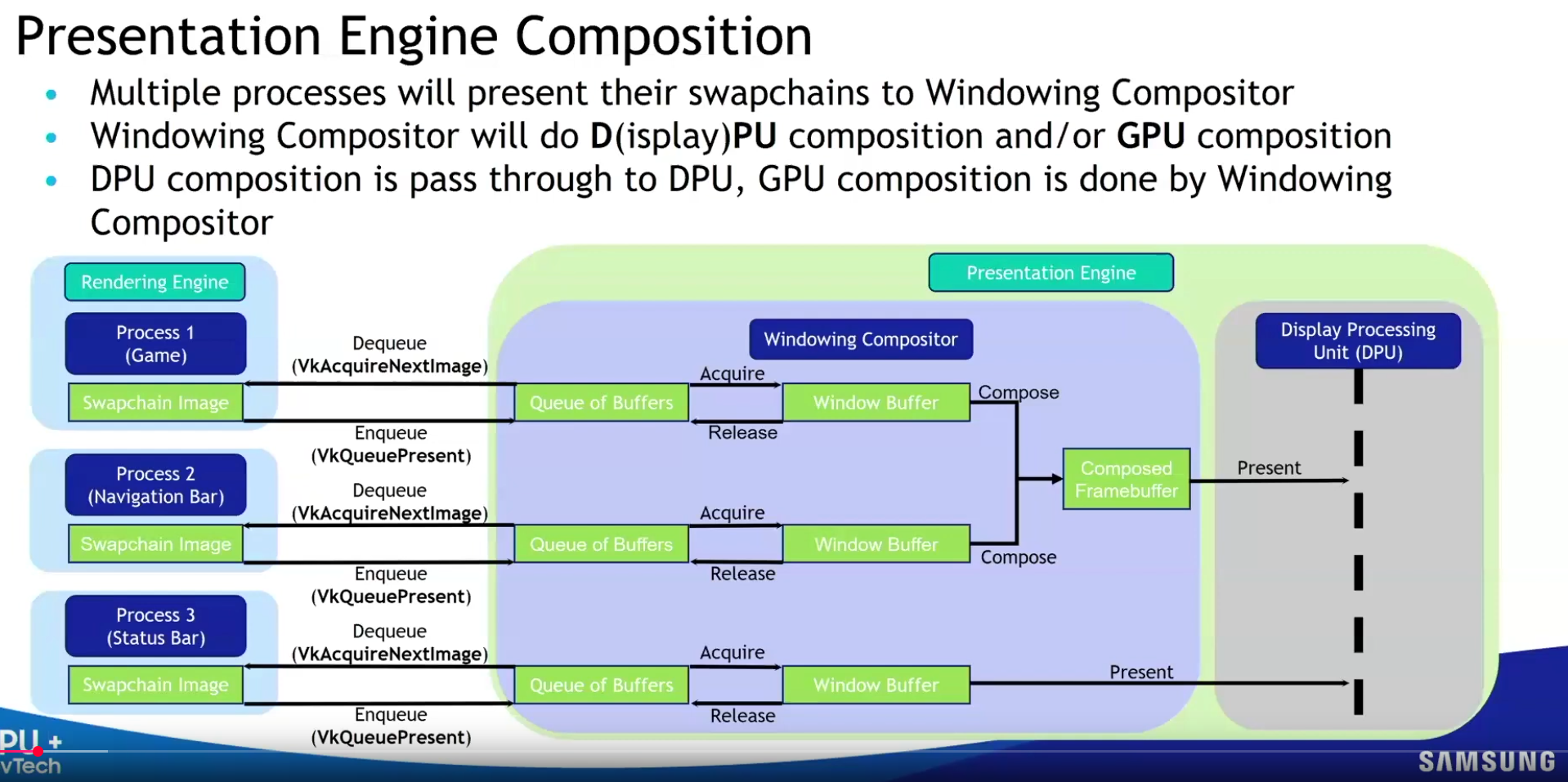 .
.
-
-
VkPresentInfoKHR-
pWaitSemaphores-
Which semaphores to wait on before presentation can happen, just like
VkSubmitInfo. -
Since we want to wait on the command buffer to finish execution, thus our triangle being drawn, we take the semaphores which will be signaled and wait on them, thus we use
signalSemaphores.
-
-
The next two parameters specify the Swapchains to present images to and the index of the image for each Swapchain.
-
This will almost always be single.
-
pResults-
It allows you to specify an array of
VkResultvalues to check for every Swapchain if presentation was successful. -
It’s not necessary if you’re only using a single Swapchain, because you can use the return value of the present function.
-
-
-
QueuePresentKHR()-
Submits a rendered image to the presentation queue.
-
Used after queueing all rendering commands and transitioning the image to the correct layout.
-
Vulkan transfers ownership of the image to the 'presentation engine'.
-
-
How a presentation happens :
-
Who :
-
The GPU (via the display controller/hardware), orchestrated by the OS/window system .
-
-
When :
-
At the next vertical blanking interval ( Vblank ).
-
Vblank is the moment between screen refreshes (e.g., at 60 Hz, every 16.67 ms).
-
-
In a Vulkan workflow, we can be sure that the presentation happened between the
QueuePresentKHR()and thevkAcquireNextImageKHR().-
The job of the
present_complete_semaphoreis to hold this information.
-
-
-
How :
-
The GPU's display controller reads the image from GPU memory.
-
The OS/window system (e.g., X11/Wayland on Linux, Win32 on Windows) composites the image into the application window.
-
The final output is scanned out to the display.
-
-
-
Image recycling :
-
After presentation, the image is released back to the swapchain.
-
It becomes available for re-acquisition via
vkAcquireNextImageKHR(after the next vblank).
-
Synchronization and Cache Control
-
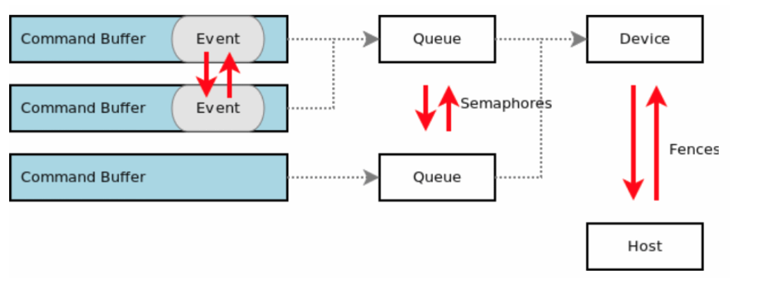 .
.
KHR_synchronization2
-
Nvidia: Use
KHR_synchronization2, the new functions allow the application to describe barriers more accurately. -
Highlights :
-
One main change with the extension is to have pipeline stages and access flags now specified together in memory barrier structures.
-
This makes the connection between the two more obvious.
-
-
Due to running out of the 32 bits for
VkAccessFlagtheVkAccessFlags2KHRtype was created with a 64-bit range. To prevent the same issue forVkPipelineStageFlags, theVkPipelineStageFlags2KHRtype was also created with a 64-bit range. -
Adds 2 new image layouts
IMAGE_LAYOUT_ATTACHMENT_OPTIMAL_KHRandIMAGE_LAYOUT_READ_ONLY_OPTIMAL_KHRto help with making layout transition easier. -
etc.
-
Queues
-
Any synchronization applies globally to a
VkQueue, there is no concept of a only-inside-this-command-buffer synchronization. -
Graphics pipelines are executable on queues supporting
QUEUE_GRAPHICS. Stages executed by graphics pipelines can only be specified in commands recorded for queues supportingQUEUE_GRAPHICS.
QueueIdle and DeviceIdle
-
These functions can be used as a very rudimentary way to perform synchronization.
-
Closing the program :
-
We should wait for the logical device to finish operations before exiting
mainLoopand destroying the window. -
You can also wait for operations in a specific command queue to be finished with
vkQueueWaitIdle. -
You’ll see that the program now exits without problems when closing the window.
-
-
Problem :
-
The problem of
vkDeviceWaitIdleorvkQueueWaitIdle, due to the lack of fences forvkQueuePresent.-
See Vulkan#Recreating , about
EXT_swapchain_maintenance1.
-
-
-
Solution :
-
Use
EXT_swapchain_maintenance1. -
See Vulkan#Recreating , for usage with swapchain.
-
-
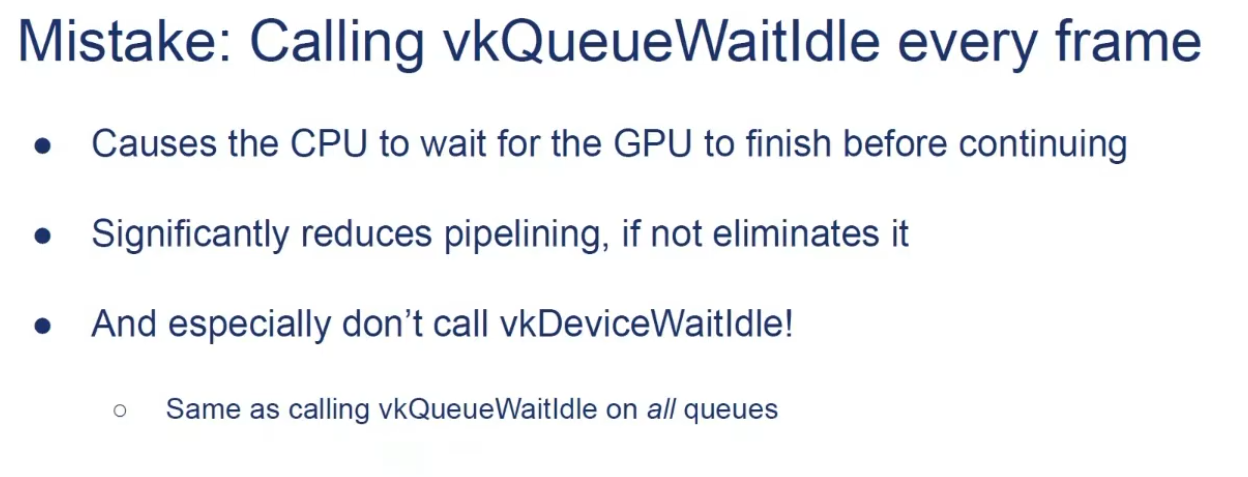 .
.
Queue Family Ownership Transfer
-
Resources created with a VkSharingMode of
SHARING_MODE_EXCLUSIVEmust have their ownership explicitly transferred from one queue family to another in order to access their content in a well-defined manner on a queue in a different queue family. -
Resources shared with external APIs or instances using external memory must also explicitly manage ownership transfers between local and external queues (or equivalent constructs in external APIs) regardless of the VkSharingMode specified when creating them.
-
If you need to transfer ownership to a different queue family, you need memory barriers, one in each queue to release/acquire ownership.
-
If memory dependencies are correctly expressed between uses of such a resource between two queues in different families, but no ownership transfer is defined, the contents of that resource are undefined for any read accesses performed by the second queue family.
-
A queue family ownership transfer consists of two distinct parts:
-
Release exclusive ownership from the source queue family
-
Is defined when
dstQueueFamilyIndexis one of those values.
-
Acquire exclusive ownership for the destination queue family
-
Is defined when
srcQueueFamilyIndexis one of those values.
-
Is defined if the values are not equal, and either is one of the special queue family values reserved for external memory ownership transfers
-
An application must ensure that these operations occur in the correct order by defining an execution dependency between them, e.g. using a semaphore.
-
A release operation is used to release exclusive ownership of a range of a buffer or image subresource range. A release operation is defined by executing a buffer memory barrier (for a buffer range) or an image memory barrier (for an image subresource range) using a pipeline barrier command, on a queue from the source queue family.
-
Etc, I haven't read much about it.
-
Command Buffers
-
The specification states that commands start execution in-order, but complete out-of-order. Don’t get confused by this. The fact that commands start in-order is simply convenient language to make the spec language easier to write.
-
Unless you add synchronization yourself, all commands in a queue execute out of order. Reordering may happen across command buffers and even
vkQueueSubmits. -
This makes sense, considering that Vulkan only sees a linear stream of commands once you submit, it is a pitfall to assume that splitting command buffers or submits adds some magic synchronization for you.
-
Frame buffer operations inside a render pass happen in API-order, of course. This is a special exception which the spec calls out.
Queue Submissions (vkQueueSubmit)
-
It automatically performs a domain operation from host to device for all writes performed before the command executes, so in most cases an explicit memory barrier is not needed for this case.
-
In the few circumstances where a submit does not occur between the host write and the device read access, writes can be made available by using an explicit memory barrier.
Example
-
vkCmdDispatch (PIPELINE_STAGE_COMPUTE_SHADER) -
vkCmdCopyBuffer (PIPELINE_STAGE_TRANSFER) -
vkCmdDispatch (PIPELINE_STAGE_COMPUTE_SHADER) -
vkCmdPipelineBarrier (srcStageMask = PIPELINE_STAGE_COMPUTE_SHADER) -
We would be referring to the two
vkCmdDispatchcommands, as they perform their work in the COMPUTE stage. Even if we split these 4 commands into 4 differentvkQueueSubmits, we would still consider the same commands for synchronization. -
Essentially, the work we are waiting for is all commands which have ever been submitted to the queue including any previous commands in the command buffer we’re recording.
Blocking Operations
-
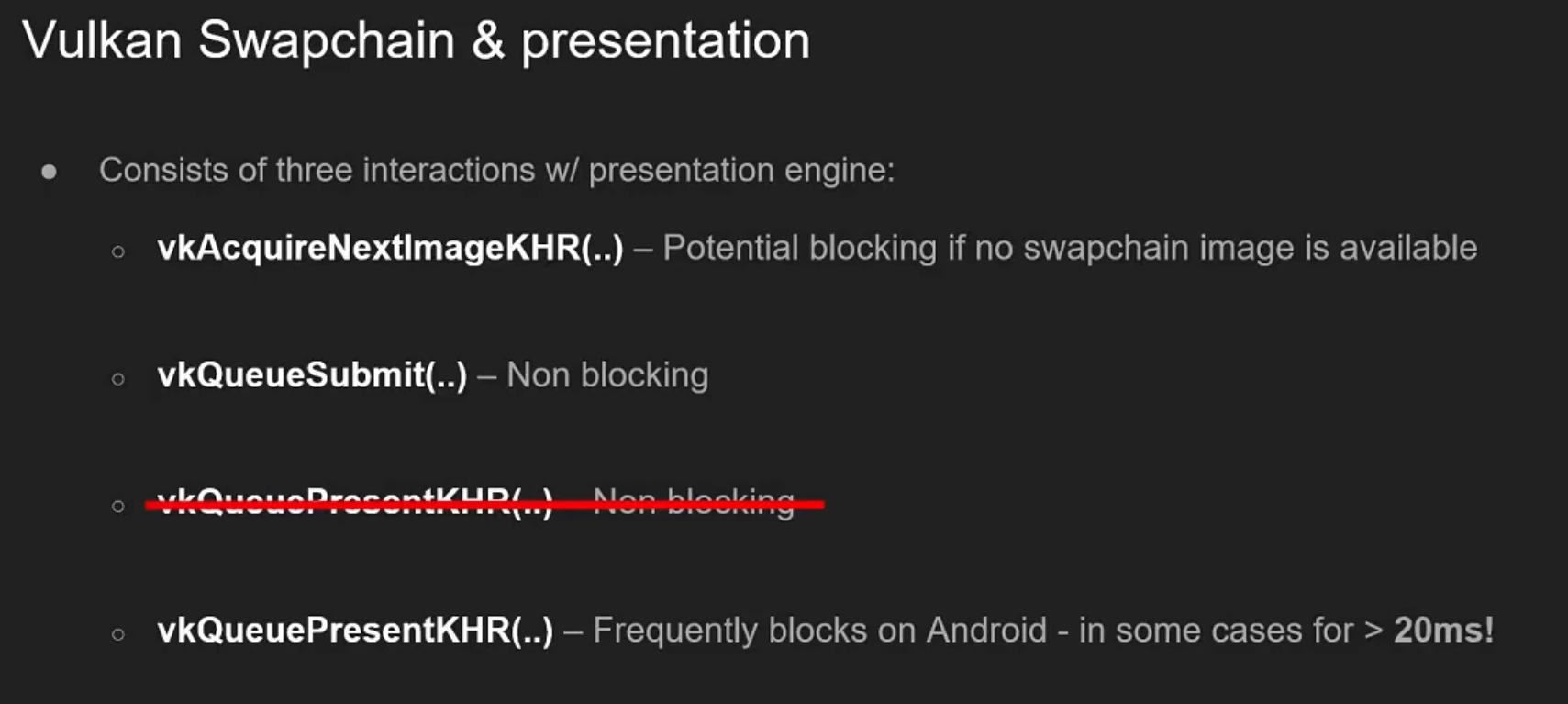 .
.
-
By Samsung 2019.
-
I don't know if this information is still valid.
-
See the Mobile section for optimizations of
vkQueuePresent.
-
Examples
-
Example 1 :
-
vkCmdDispatch– writes to an SSBO,ACCESS_SHADER_WRITE -
vkCmdPipelineBarrier(srcStageMask = COMPUTE, dstStageMask = TRANSFER, srcAccessMask = SHADER_WRITE, dstAccessMask = 0) -
vkCmdPipelineBarrier(srcStageMask = TRANSFER, dstStageMask = COMPUTE, srcAccessMask = 0, dstAccessMask = SHADER_READ) -
vkCmdDispatch– read from the same SSBO,ACCESS_SHADER_READ -
While
StageMaskcannot be 0,AccessMaskcan be 0.
-
-
Recently allocated image, to use in a compute shader as a storage image :
-
The pipeline barrier looks like:
-
oldLayout = UNDEFINED-
Input is garbage
-
-
newLayout = GENERAL-
Storage image compatible layout
-
-
srcStageMask = TOP_OF_PIPE-
Wait for nothing
-
-
srcAccessMask = 0-
This is key, there are no pending writes to flush out.
-
This is the only way to use
TOP_OF_PIPEin a memory barrier.
-
-
dstStageMask = COMPUTE-
Unblock compute after the layout transition is done
-
-
dstAccessMask = SHADER_READ | SHADER_WRITE
-
-
-
Swapchain Image Transition to PRESENT_SRC :
-
We have to transition them into
IMAGE_LAYOUT_PRESENT_SRCbefore passing the image over to the presentation engine. -
Having
dstStageMask = BOTTOM_OF_PIPEanddstAccessMask = 0is perfectly fine. We don’t care about making this memory visible to any stage beyond this point. We will use semaphores to synchronize with the presentation engine anyways. -
The pipeline barrier looks like:
-
srcStageMask = COLOR_ATTACHMENT_OUTPUT-
Assuming we rendered to swapchain in a render pass.
-
-
srcAccessMask = COLOR_ATTACHMENT_WRITE -
dstStageMask = BOTTOM_OF_PIPE-
After transitioning into this
PRESENTlayout, we’re not going to touch the image again until we reacquire the image, sodstStageMask = BOTTOM_OF_PIPEis appropriate.
-
-
dstAccessMask = 0 -
oldLayout = COLOR_ATTACHMENT_OPTIMAL -
newLayout = PRESENT_SRC_KHR
-
-
Setting
dstAccessMask = 0on the finalTRANSFER_DST → PRESENT_SRC_KHRbarrier means “there is no GPU access after this barrier that we are ordering/expressing.” For swapchain-present that is intentional and common: presentation is outside the GPU pipeline, so the barrier only needs to make the producer writes (e.g. your blitTRANSFER_WRITE) available/visible; the presentation engine performs its own, external visibility semantics.
-
-
Example 1 :
-
vkCmdPipelineBarrier(srcStageMask = FRAGMENT_SHADER, dstStageMask = ?) -
Vertex shading for future commands can begin executing early, we only need to wait once
FRAGMENT_SHADERis reached.
-
-
Example 2 :
-
vkCmdDispatch -
vkCmdDispatch -
vkCmdDispatch -
vkCmdPipelineBarrier(srcStageMask = COMPUTE, dstStageMask = COMPUTE) -
vkCmdDispatch -
vkCmdDispatch -
vkCmdDispatch
-
{5, 6, 7} must wait for {1, 2, 3}.
-
A possible execution order here could be:
-
#3
-
#2
-
#1
-
#7
-
#6
-
#5
-
-
{1, 2, 3} can execute out-of-order, and so can {5, 6, 7}, but these two sets of commands can not interleave execution.
-
In spec lingo {1, 2, 3} happens-before {5, 6, 7}.
-
-
Chain of Dependencies (1) :
-
vkCmdDispatch -
vkCmdDispatch -
vkCmdPipelineBarrier(srcStageMask = COMPUTE, dstStageMask = TRANSFER) -
vkCmdPipelineBarrier(srcStageMask = TRANSFER, dstStageMask = COMPUTE) -
vkCmdDispatch -
vkCmdDispatch
-
{5, 6} must wait for {1, 2}.
-
We created a chain of dependencies between COMPUTE -> TRANSFER -> COMPUTE.
-
When we wait for TRANSFER in 4, we must also wait for anything which is currently blocking TRANSFER.
-
-
Chain of dependencies (2) :
-
vkCmdDispatch -
vkCmdDispatch -
vkCmdPipelineBarrier(srcStageMask = COMPUTE, dstStageMask = TRANSFER) -
vkCmdMagicDummyTransferOperation -
vkCmdPipelineBarrier(srcStageMask = TRANSFER, dstStageMask = COMPUTE) -
vkCmdDispatch -
vkCmdDispatch
-
{4} must wait for {1, 2}.
-
{6, 7} must wait for {4}.
-
The chain is {1, 2} -> {4} -> {6, 7}, and if {4} is noop (no operation), {1, 2} -> {6, 7} is achieved.
-
Execution Dependencies, Memory Dependencies, Memory Model
Data hazards
-
Execution dependencies and memory dependencies are used to solve data hazards, i.e. to ensure that read and write operations occur in a well-defined order.
-
An operation is an arbitrary amount of work to be executed on the host, a device, or an external entity such as a presentation engine.
-
-
Write-after-read hazards :
-
Can be solved with just an execution dependency
-
-
Read-after-write hazards :
-
Need appropriate memory dependencies to be included between them.
-
-
Write-after-write hazards :
-
Need appropriate memory dependencies to be included between them.
-
-
If an application does not include dependencies to solve these hazards, the results and execution orders of memory accesses are undefined .
Execution Dependencies
-
An execution dependency is a guarantee that for two sets of operations, the first set must happen-before the second set. If an operation happens-before another operation, then the first operation must complete before the second operation is initiated.
-
Execution dependencies alone are not sufficient to guarantee that values resulting from writes in one set of operations can be read from another set of operations.
Memory Available
-
Availability operations cause the values generated by specified memory write accesses to become available for future access.
-
Any available value remains available until a subsequent write to the same memory location occurs (whether it is made available or not) or the memory is freed.
-
Availability operations :
-
Cause the values generated by specified memory write accesses to become available to a memory domain for future access. Any available value remains available until a subsequent write to the same memory location occurs (whether it is made available or not) or the memory is freed.
-
Even with coherent mapping, you still need to have a dependency between the host writing that memory and the GPU operation reading it.
-
-
We can say “making memory available” is all about flushing caches.
-
-
Guarantees that host writes to the memory ranges described by
pMemoryRangescan be made available to device access, via availability operations from theACCESS_HOST_WRITEaccess type. -
This is required for CPU writes, which
HOST_COHERENTeffectively provides.
-
-
Cache example :
-
When our L2 cache contains the most up-to-date data there is, we can say that memory is available , as L1 caches connected to L2 can pull in the most up-to-date data there is.
-
Once a shader stage writes to memory, the L2 cache no longer has the most up-to-date data there is, so that memory is no longer considered available .
-
If other caches try to read from L2, it will see undefined data.
-
Whatever wrote that data must make those writes available before the data can be made visible again.
-
-
Memory Domain
-
Memory domain operations :
-
Cause writes that are available to a source memory domain to become available to a destination memory domain (an example of this is making writes available to the host domain available to the device domain).
-
Memory Visible
-
Visibility operations :
-
Cause values available to a memory domain to become visible to specified memory accesses.
-
Memory barriers are visibility operations. Without them, you wouldn’t have visibility of the memory.
-
The execution barrier ensures the completion of a command, but the
srcStageMask,dstStageMask,srcAccessMaskanddstAccessMaskare what handles availability.
-
-
-
Once written values are made visible to a particular type of memory access, they can be read or written by that type of memory access.
-
We can say “making memory visible” is all about invalidating caches.
-
Availability is a necessary part of visibility, but availability alone is not sufficient.
-
You can do things that might have caused visibility, but because the write was not available, they don’t actually make the write visible.
-
-
Under the hood, visibility is implementation-specific. The pure-visibility parts typically involve forcing lines out of caches and/or invalidating them. But some kinds of visibility may not require even that.
-
vkInvalidateMappedMemoryRanges().-
Guarantees that device writes to the memory ranges described by
pMemoryRanges, which have been made available to the host memory domain using theACCESS_HOST_WRITEandACCESS_HOST_READaccess types, are made visible to the host. -
If a range of non-coherent memory is written by the host and then invalidated without first being flushed, its contents are undefined.
-
Host Coherent
-
MEMORY_PROPERTY_HOST_COHERENT-
If a memory object does have this property:
-
Writes to the memory object from the host are automatically made available to the host domain.
-
It says that you don't need
vkFlushMappedMemoryRanges()orvkInvalidateMappedMemoryRanges(). -
This property alone is insufficient for availability. You still need to use synchronization to make sure that reads and writes from CPU and GPU happen in the right order, and you need memory barriers on the GPU side to manage GPU caches (make CPU writes visible to GPU reads, and make GPU writes available to CPU reads).
-
Coherency is about "visibility", but you still need availability.
-
-
If a memory object does not have this property:
-
vkFlushMappedMemoryRanges()must be called in order to guarantee that writes to the memory object from the host are made available to the host domain, where they can be further made available to the device domain via a domain operation. -
vkInvalidateMappedMemoryRanges()must be called to guarantee that writes which are available to the host domain are made visible to host operations.
-
-
Memory Dependency
-
Memory Dependency is an execution dependency which includes availability and visibility operations such that:
-
The first set of operations happens-before the availability operation.
-
The availability operation happens-before the visibility operation.
-
The visibility operation happens-before the second set of operations.
-
-
It enforces availability and visibility of memory accesses and execution order between two sets of operations.
-
Most synchronization commands in Vulkan define a memory dependency.
-
The specific memory accesses that are made available and visible are defined by the access scopes of a memory dependency.
-
Any type of access that is in a memory dependency’s first access scope is made available .
-
Any type of access that is in a memory dependency’s second access scope has any available writes made visible to it.
-
Any type of operation that is not in a synchronization command’s access scopes will not be included in the resulting dependency.
Execution Stages
-
The Stage Masks are a bit-mask, so it’s perfectly fine to wait for both X and Y work.
-
By specifying the source and target stages, you tell the driver what operations need to finish before the transition can execute, and what must not have started yet.
-
Nvidia: Use optimal
srcStageMaskanddstStageMask. Most important cases: If the specified resources are accessed only in compute or fragment shaders, use the compute or the fragment stage bits for both masks, to make the barrier fragment-only or compute-only. -
Caio: "Wait for
srcStageMaskto finish, beforedstStageMaskcan start". -
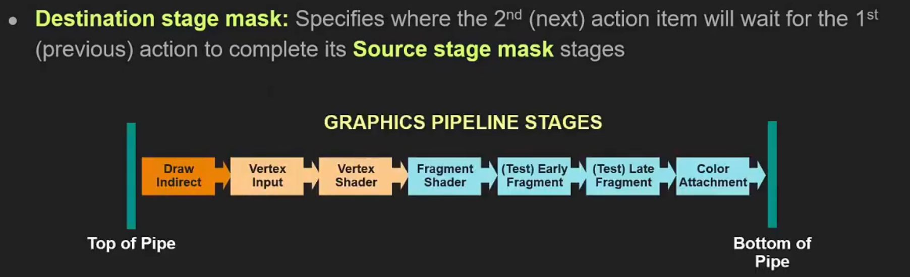 .
.
-
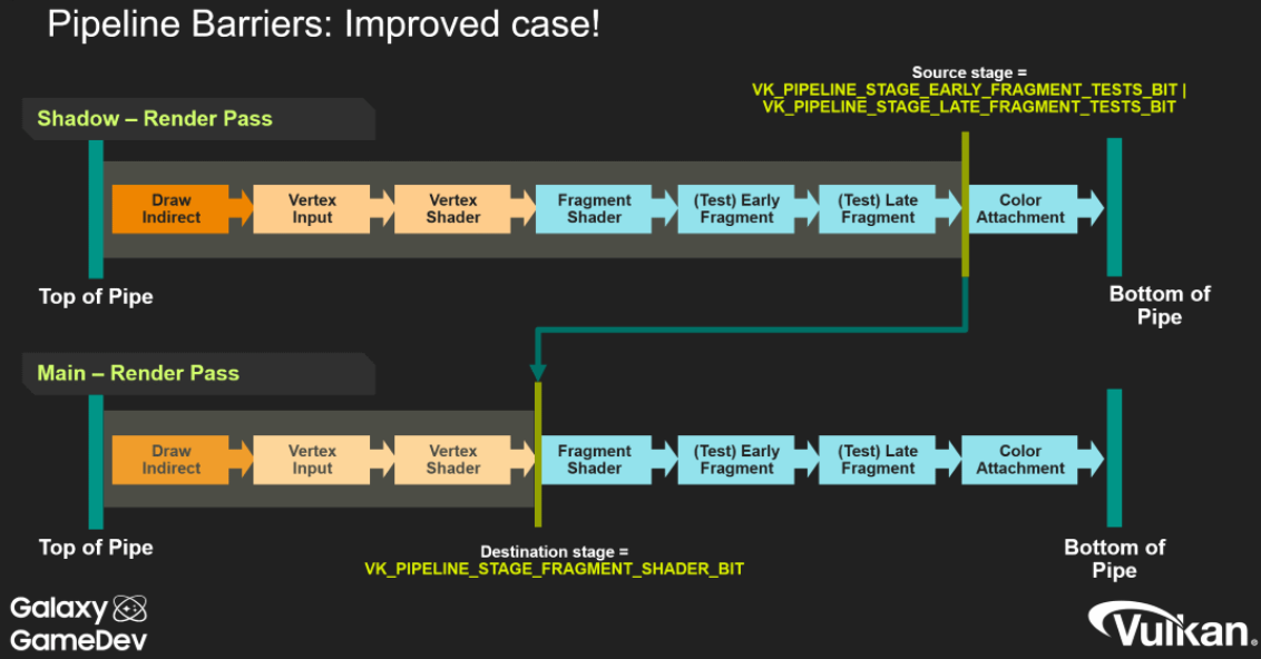 .
.
-
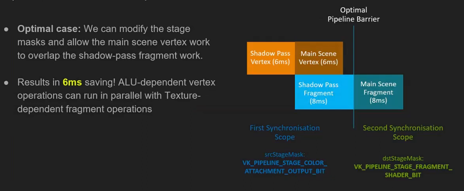 .
.
-
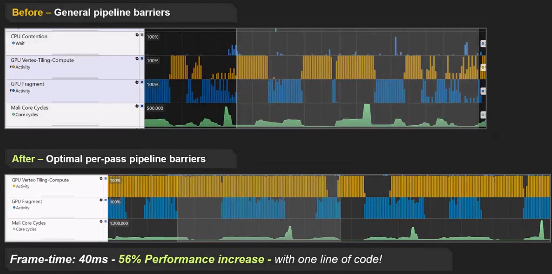 .
.
First synchronization scope
-
srcStageMask -
This represents what we are waiting for.
-
"What operations need to finish before the transition can execute".
Second synchronization scope
-
dstStageMask -
"What operations must not have started yet".
-
Any work submitted after this barrier will need to wait for the work represented by
srcStageMaskbefore it can execute.
Stages
-
TOP_OF_PIPEandBOTTOM_OF_PIPE:-
These stages are essentially “helper” stages, which do no actual work, but serve some important purposes. Every command will first execute the
TOP_OF_PIPEstage. This is basically the command processor on the GPU parsing the command.BOTTOM_OF_PIPEis where commands retire after all work has been done. -
Both these pipeline stages are deprecated, and applications should prefer
ALL_COMMANDSandNONE. -
Memory Access :
-
Never use
AccessMask != 0with these stages. These stages do not perform memory accesses . AnysrcAccessMaskanddstAccessMaskcombination with either stage will be meaningless, and spec disallows this. -
TOP_OF_PIPEandBOTTOM_OF_PIPEare purely there for the sake of execution barriers, not memory barriers.
-
-
-
TOP_OF_PIPE-
In the first scope:
-
Equivalent to
NONE -
Is basically saying “wait for nothing”, or to be more precise, we’re waiting for the GPU to parse all commands.
-
We had to parse all commands before getting to the pipeline barrier command to begin with.
-
-
-
In the second scope:
-
Equivalent to
ALL_COMMANDSwithVkAccessFlags2set to0.
-
-
-
BOTTOM_OF_PIPE-
In the first scope:
-
Equivalent to
ALL_COMMANDS, withVkAccessFlags2set to0.
-
-
In the second scope:
-
Equivalent to
NONE. -
Basically translates to “block the last stage of execution in the pipeline”.
-
“No work after this barrier is going to wait for us”.
-
-
-
NONE-
Specifies no stages of execution.
-
-
ALL_COMMANDS-
Specifies all operations performed by all commands supported on the queue it is used with.
-
Basically drains the entire queue for work.
-
-
ALL_GRAPHICS-
Specifies the execution of all graphics pipeline stages.
-
It's the same as
ALL_COMMANDS, but only for render passes. -
Is equivalent to the logical OR of:
-
DRAW_INDIRECT -
COPY_INDIRECT -
TASK_SHADER -
MESH_SHADER -
VERTEX_INPUT -
VERTEX_SHADER -
TESSELLATION_CONTROL_SHADER -
TESSELLATION_EVALUATION_SHADER -
GEOMETRY_SHADER -
FRAGMENT_SHADER -
EARLY_FRAGMENT_TESTS -
LATE_FRAGMENT_TESTS -
COLOR_ATTACHMENT_OUTPUT -
CONDITIONAL_RENDERING -
TRANSFORM_FEEDBACK -
FRAGMENT_SHADING_RATE_ATTACHMENT -
FRAGMENT_DENSITY_PROCESS -
SUBPASS_SHADER -
INVOCATION_MASK -
CLUSTER_CULLING_SHADER
-
-
Order of execution stages
-
Ignoring
TOP_OF_PIPEandBOTTOM_OF_PIPE. -
Graphics primitive pipeline :
-
DRAW_INDIRECT-
Parses indirect buffers.
-
-
COPY_INDIRECT -
INDEX_INPUT -
VERTEX_ATTRIBUTE_INPUT-
Consumes fixed function VBOs and IBOs
-
-
VERTEX_SHADER -
TESSELLATION_CONTROL_SHADER -
TESSELLATION_EVALUATION_SHADER -
GEOMETRY_SHADER -
TRANSFORM_FEEDBACK -
FRAGMENT_SHADING_RATE_ATTACHMENT -
EARLY_FRAGMENT_TESTS-
Early depth/stencil tests.
-
Render pass performs its
loadOpof a depth/stencil attachment. -
This stage isn’t all that useful or meaningful except in some very obscure scenarios with frame buffer self-dependencies (aka,
GL_ARB_texture_barrier). -
When blocking a render pass with
dstStageMask, just use a mask ofEARLY_FRAGMENT_TESTS | LATE_FRAGMENT_TESTS. -
dstStageMask = EARLY_FRAGMENT_TESTSalone might work since that will blockloadOp, but there might be shenanigans with memory barriers if you are 100% pedantic about any memory access happening inLATE_FRAGMENT_TESTS. If you’re blocking an early stage, it never hurts to block a later stage as well.
-
-
FRAGMENT_SHADER -
LATE_FRAGMENT_TESTS-
Late depth-stencil tests.
-
Render pass performs its
storeOpof a depth/stencil attachment when a render pass is done. -
When you’re waiting for a depth map to have been rendered in an earlier render pass, you should use
srcStageMask = LATE_FRAGMENT_TESTS, as that will wait for thestoreOpto finish its work.
-
-
COLOR_ATTACHMENT_OUTPUT-
This one is where
loadOp,storeOp, MSAA resolves and frame buffer blend stage takes place. -
Basically anything that touches a color attachment in a render pass in some way.
-
If you’re waiting for a render pass which uses color to be complete, use
srcStageMask = COLOR_ATTACHMENT_OUTPUT, and similar fordstStageMaskwhen blocking render passes from execution. -
Usage as
dstStageMask:-
COLOR_ATTACHMENT_OUTPUTis the appropriatedstStageMaskwhen you are transitioning an image so it can be written as a color attachment.
-
-
-
-
Graphics mesh pipeline :
-
DRAW_INDIRECT -
TASK_SHADER -
MESH_SHADER -
FRAGMENT_SHADING_RATE_ATTACHMENT -
EARLY_FRAGMENT_TESTS -
FRAGMENT_SHADER -
LATE_FRAGMENT_TESTS -
COLOR_ATTACHMENT_OUTPUT
-
-
Compute pipeline :
-
DRAW_INDIRECT -
COPY_INDIRECT -
COMPUTE_SHADER
-
-
Transfer pipeline :
-
COPY_INDIRECT -
TRANSFER
-
-
Subpass shading pipeline :
-
SUBPASS_SHADER
-
-
Graphics pipeline commands executing in a render pass with a fragment density map attachment : (almost unordered)
-
The following pipeline stage where the fragment density map read happens has no particular order relative to the other stages.
-
It is logically earlier than
EARLY_FRAGMENT_TESTS, so:-
FRAGMENT_DENSITY_PROCESS -
EARLY_FRAGMENT_TESTS
-
-
-
Conditional rendering stage : (unordered)
-
Is formally part of both the graphics, and the compute pipeline.
-
The predicate read has unspecified order relative to other stages of these pipelines:
-
CONDITIONAL_RENDERING
-
-
Host operations :
-
Only one pipeline stage occurs.
-
HOST
-
-
Command preprocessing pipeline :
-
COMMAND_PREPROCESS
-
-
Acceleration structure build operations :
-
Only one pipeline stage occurs.
-
ACCELERATION_STRUCTURE_BUILD
-
-
Acceleration structure copy operations :
-
Only one pipeline stage occurs.
-
ACCELERATION_STRUCTURE_COPY
-
-
Opacity micromap build operations :
-
Only one pipeline stage occurs.
-
MICROMAP_BUILD
-
-
Ray tracing pipeline :
-
DRAW_INDIRECT -
RAY_TRACING_SHADER
-
-
Video decode pipeline :
-
VIDEO_DECODE
-
-
Video encode pipeline :
-
VIDEO_ENCODE
-
-
Data graph pipeline :
-
DATA_GRAPH
-
Memory Access
-
Access scopes do not interact with the logically earlier or later stages for either scope - only the stages the application specifies are considered part of each access scope.
-
These flags represent memory access that can be performed.
-
Each pipeline stage can perform certain memory accesses, and thus we take the combination of pipeline stage + access mask and we get potentially a very large number of incoherent caches on the system.
-
Each GPU core has its own set of L1 caches as well.
-
Real GPUs will only have a fraction of the possible caches here, but as long as we are explicit about this in the API, any GPU driver can simplify this as needed.
-
Access masks either read from a cache, or write to an L1 cache in our mental model.
-
Certain access types are only performed by a subset of pipeline stages.
-
"Had this access (
srcAccessMask) and it's going to have this access (dstAccessMask)". -
srcAccessMask-
Lists the access types that happened before the barrier (the producer accesses) and that must be made available/visible by the barrier.
-
Must describe the kinds of accesses that actually happened before the barrier (the producer accesses you need to make available/visible) .
-
It does not describe what you want the resource to become after the barrier — that is expressed by
dstAccessMask(what will happen after). -
The stage masks (src/dst stage) specify the pipeline stages that contain those accesses.
-
srcAccessMask = 0means “there are no prior GPU memory accesses that this barrier needs to make available” (i.e. nothing to claim as the producer side).
-
-
dstAccessMask-
Lists the access types that will happen after the barrier (the consumer accesses) and that must see the producer’s writes.
-
dstAccessMask = 0means “there are no subsequent GPU memory accesses that this barrier needs to order/make visible to” (i.e. no GPU consumer to describe with access bits).
-
Access Flags
-
MEMORY_READ-
Specifies all read accesses.
-
It is always valid in any access mask, and is treated as equivalent to setting all
READaccess flags that are valid where it is used.
-
-
MEMORY_WRITE-
Specifies all write accesses.
-
It is always valid in any access mask, and is treated as equivalent to setting all
WRITEaccess flags that are valid where it is used.
-
-
SHADER_READ-
Same as
SAMPLED_READ+STORAGE_READ+TILE_ATTACHMENT_READ.
-
-
SHADER_SAMPLED_READ-
Specifies read access to a uniform texel buffer or sampled image in any shader pipeline stage.
-
-
HOST_READ-
Specifies read access by a host operation. Accesses of this type are not performed through a resource, but directly on memory.
-
Such access occurs in the
PIPELINE_STAGE_2_HOSTpipeline stage.
-
-
HOST_WRITE-
Specifies write access by a host operation. Accesses of this type are not performed through a resource, but directly on memory.
-
Such access occurs in the
PIPELINE_STAGE_2_HOSTpipeline stage.
-
Access Flag -> Pipeline Stages
| Access flag | Pipeline stages |
|-----------------------------------------|---------------------------------------------------------------------------------------------------------------------------------------------------------------------------------------------------------------------------------------------------------------------------------------------------------|
|
NONE
| Any |
|
INDIRECT_COMMAND_READ
|
DRAW_INDIRECT
,
ACCELERATION_STRUCTURE_BUILD
,
COPY_INDIRECT
|
|
INDEX_READ
|
VERTEX_INPUT
,
INDEX_INPUT
|
|
VERTEX_ATTRIBUTE_READ
|
VERTEX_INPUT
,
VERTEX_ATTRIBUTE_INPUT
|
|
UNIFORM_READ
|
VERTEX_SHADER
,
TESSELLATION_CONTROL_SHADER
,
TESSELLATION_EVALUATION_SHADER
,
GEOMETRY_SHADER
,
FRAGMENT_SHADER
,
COMPUTE_SHADER
,
RAY_TRACING_SHADER
,
TASK_SHADER
,
MESH_SHADER
,
SUBPASS_SHADER
,
CLUSTER_CULLING_SHADER
|
|
INPUT_ATTACHMENT_READ
|
FRAGMENT_SHADER
,
SUBPASS_SHADER
|
|
SHADER_READ
|
ACCELERATION_STRUCTURE_BUILD
,
MICROMAP_BUILD
,
VERTEX_SHADER
,
TESSELLATION_CONTROL_SHADER
,
TESSELLATION_EVALUATION_SHADER
,
GEOMETRY_SHADER
,
FRAGMENT_SHADER
,
COMPUTE_SHADER
,
RAY_TRACING_SHADER
,
TASK_SHADER
,
MESH_SHADER
,
SUBPASS_SHADER
,
CLUSTER_CULLING_SHADER
|
|
SHADER_WRITE
|
VERTEX_SHADER
,
TESSELLATION_CONTROL_SHADER
,
TESSELLATION_EVALUATION_SHADER
,
GEOMETRY_SHADER
,
FRAGMENT_SHADER
,
COMPUTE_SHADER
,
RAY_TRACING_SHADER
,
TASK_SHADER
,
MESH_SHADER
,
SUBPASS_SHADER
,
CLUSTER_CULLING_SHADER
|
|
COLOR_ATTACHMENT_READ
|
FRAGMENT_SHADER
,
COLOR_ATTACHMENT_OUTPUT
|
|
COLOR_ATTACHMENT_WRITE
|
COLOR_ATTACHMENT_OUTPUT
|
|
DEPTH_STENCIL_ATTACHMENT_READ
|
FRAGMENT_SHADER
,
EARLY_FRAGMENT_TESTS
,
LATE_FRAGMENT_TESTS
|
|
DEPTH_STENCIL_ATTACHMENT_WRITE
|
EARLY_FRAGMENT_TESTS
,
LATE_FRAGMENT_TESTS
|
|
TRANSFER_READ
|
ALL_TRANSFER
,
COPY
,
RESOLVE
,
BLIT
,
ACCELERATION_STRUCTURE_BUILD
,
ACCELERATION_STRUCTURE_COPY
,
MICROMAP_BUILD
,
CONVERT_COOPERATIVE_VECTOR_MATRIX
|
|
TRANSFER_WRITE
|
ALL_TRANSFER
,
COPY
,
RESOLVE
,
BLIT
,
CLEAR
,
ACCELERATION_STRUCTURE_BUILD
,
ACCELERATION_STRUCTURE_COPY
,
MICROMAP_BUILD
,
CONVERT_COOPERATIVE_VECTOR_MATRIX
|
|
HOST_READ
|
HOST
|
|
HOST_WRITE
|
HOST
|
|
MEMORY_READ
| Any |
|
MEMORY_WRITE
| Any |
|
SHADER_SAMPLED_READ
|
VERTEX_SHADER
,
TESSELLATION_CONTROL_SHADER
,
TESSELLATION_EVALUATION_SHADER
,
GEOMETRY_SHADER
,
FRAGMENT_SHADER
,
COMPUTE_SHADER
,
RAY_TRACING_SHADER
,
TASK_SHADER
,
MESH_SHADER
,
SUBPASS_SHADER
,
CLUSTER_CULLING_SHADER
|
|
SHADER_STORAGE_READ
|
VERTEX_SHADER
,
TESSELLATION_CONTROL_SHADER
,
TESSELLATION_EVALUATION_SHADER
,
GEOMETRY_SHADER
,
FRAGMENT_SHADER
,
COMPUTE_SHADER
,
RAY_TRACING_SHADER
,
TASK_SHADER
,
MESH_SHADER
,
SUBPASS_SHADER
,
CLUSTER_CULLING_SHADER
|
|
SHADER_STORAGE_WRITE
|
VERTEX_SHADER
,
TESSELLATION_CONTROL_SHADER
,
TESSELLATION_EVALUATION_SHADER
,
GEOMETRY_SHADER
,
FRAGMENT_SHADER
,
COMPUTE_SHADER
,
RAY_TRACING_SHADER
,
TASK_SHADER
,
MESH_SHADER
,
SUBPASS_SHADER
,
CLUSTER_CULLING_SHADER
|
|
VIDEO_DECODE_READ
|
VIDEO_DECODE
|
|
VIDEO_DECODE_WRITE
|
VIDEO_DECODE
|
|
VIDEO_ENCODE_READ
|
VIDEO_ENCODE
|
|
VIDEO_ENCODE_WRITE
|
VIDEO_ENCODE
|
|
TRANSFORM_FEEDBACK_WRITE
|
TRANSFORM_FEEDBACK
|
|
TRANSFORM_FEEDBACK_COUNTER_READ
|
DRAW_INDIRECT
,
TRANSFORM_FEEDBACK
|
|
TRANSFORM_FEEDBACK_COUNTER_WRITE
|
TRANSFORM_FEEDBACK
|
|
CONDITIONAL_RENDERING_READ
|
CONDITIONAL_RENDERING
|
|
COMMAND_PREPROCESS_READ
|
COMMAND_PREPROCESS
|
|
COMMAND_PREPROCESS_WRITE
|
COMMAND_PREPROCESS
|
|
FRAGMENT_SHADING_RATE_ATTACHMENT_READ
|
FRAGMENT_SHADING_RATE_ATTACHMENT
|
|
ACCELERATION_STRUCTURE_READ
|
VERTEX_SHADER
,
TESSELLATION_CONTROL_SHADER
,
TESSELLATION_EVALUATION_SHADER
,
GEOMETRY_SHADER
,
FRAGMENT_SHADER
,
COMPUTE_SHADER
,
RAY_TRACING_SHADER
,
TASK_SHADER
,
MESH_SHADER
,
CLUSTER_CULLING_SHADER
,
ACCELERATION_STRUCTURE_BUILD
,
ACCELERATION_STRUCTURE_COPY
,
SUBPASS_SHADER
|
|
ACCELERATION_STRUCTURE_WRITE
|
ACCELERATION_STRUCTURE_BUILD
,
ACCELERATION_STRUCTURE_COPY
|
|
FRAGMENT_DENSITY_MAP_READ
|
FRAGMENT_DENSITY_PROCESS
|
|
COLOR_ATTACHMENT_READ_NONCOHERENT
|
COLOR_ATTACHMENT_OUTPUT
|
|
DESCRIPTOR_BUFFER_READ
|
VERTEX_SHADER
,
TESSELLATION_CONTROL_SHADER
,
TESSELLATION_EVALUATION_SHADER
,
GEOMETRY_SHADER
,
FRAGMENT_SHADER
,
COMPUTE_SHADER
,
RAY_TRACING_SHADER
,
TASK_SHADER
,
MESH_SHADER
,
SUBPASS_SHADER
,
CLUSTER_CULLING_SHADER
|
|
INVOCATION_MASK_READ
|
INVOCATION_MASK
|
|
MICROMAP_READ
|
MICROMAP_BUILD
,
ACCELERATION_STRUCTURE_BUILD
|
|
MICROMAP_WRITE
|
MICROMAP_BUILD
|
|
OPTICAL_FLOW_READ
|
OPTICAL_FLOW
|
|
OPTICAL_FLOW_WRITE
|
OPTICAL_FLOW
|
|
SHADER_TILE_ATTACHMENT_READ
|
FRAGMENT_SHADER
,
COMPUTE_SHADER
|
|
SHADER_TILE_ATTACHMENT_WRITE
|
FRAGMENT_SHADER
,
COMPUTE_SHADER
|
|
DATA_GRAPH_READ
|
DATA_GRAPH
|
|
DATA_GRAPH_WRITE
|
DATA_GRAPH
|
Pipeline Stage -> Access Flags
| Pipeline stage | Access flags |
| ----------------------------------- | ------------------------------------------------------------------------------------------------------------------------------------------------------------------------------------------------------------------------------------------------------------------------------------------------------------------------------ |
|
ACCELERATION_STRUCTURE_BUILD
|
ACCELERATION_STRUCTURE_READ
,
ACCELERATION_STRUCTURE_WRITE
,
INDIRECT_COMMAND_READ
,
MICROMAP_READ
,
SHADER_READ
,
TRANSFER_READ
,
TRANSFER_WRITE
|
|
ACCELERATION_STRUCTURE_COPY
|
ACCELERATION_STRUCTURE_READ
,
ACCELERATION_STRUCTURE_WRITE
,
TRANSFER_READ
,
TRANSFER_WRITE
|
|
ALL_TRANSFER
|
TRANSFER_READ
,
TRANSFER_WRITE
|
|
ANY
|
MEMORY_READ
,
MEMORY_WRITE
,
NONE
|
|
BLIT
|
TRANSFER_READ
,
TRANSFER_WRITE
|
|
CLEAR
|
TRANSFER_WRITE
|
|
CLUSTER_CULLING_SHADER
|
ACCELERATION_STRUCTURE_READ
,
DESCRIPTOR_BUFFER_READ
,
SHADER_READ
,
SHADER_SAMPLED_READ
,
SHADER_STORAGE_READ
,
SHADER_STORAGE_WRITE
,
SHADER_WRITE
,
UNIFORM_READ
|
|
COLOR_ATTACHMENT_OUTPUT
|
COLOR_ATTACHMENT_READ
,
COLOR_ATTACHMENT_READ_NONCOHERENT
,
COLOR_ATTACHMENT_WRITE
|
|
COMMAND_PREPROCESS
|
COMMAND_PREPROCESS_READ
,
COMMAND_PREPROCESS_WRITE
|
|
COMPUTE_SHADER
|
ACCELERATION_STRUCTURE_READ
,
DESCRIPTOR_BUFFER_READ
,
SHADER_READ
,
SHADER_SAMPLED_READ
,
SHADER_STORAGE_READ
,
SHADER_STORAGE_WRITE
,
SHADER_TILE_ATTACHMENT_READ
,
SHADER_TILE_ATTACHMENT_WRITE
,
SHADER_WRITE
,
UNIFORM_READ
|
|
CONDITIONAL_RENDERING
|
CONDITIONAL_RENDERING_READ
|
|
CONVERT_COOPERATIVE_VECTOR_MATRIX
|
TRANSFER_READ
,
TRANSFER_WRITE
|
|
COPY
|
TRANSFER_READ
,
TRANSFER_WRITE
|
|
COPY_INDIRECT
|
INDIRECT_COMMAND_READ
|
|
DATA_GRAPH
|
DATA_GRAPH_READ
,
DATA_GRAPH_WRITE
|
|
DRAW_INDIRECT
|
INDIRECT_COMMAND_READ
,
TRANSFORM_FEEDBACK_COUNTER_READ
|
|
EARLY_FRAGMENT_TESTS
|
DEPTH_STENCIL_ATTACHMENT_READ
,
DEPTH_STENCIL_ATTACHMENT_WRITE
|
|
FRAGMENT_DENSITY_PROCESS
|
FRAGMENT_DENSITY_MAP_READ
|
|
FRAGMENT_SHADER
|
ACCELERATION_STRUCTURE_READ
,
COLOR_ATTACHMENT_READ
,
DEPTH_STENCIL_ATTACHMENT_READ
,
DESCRIPTOR_BUFFER_READ
,
INPUT_ATTACHMENT_READ
,
SHADER_READ
,
SHADER_SAMPLED_READ
,
SHADER_STORAGE_READ
,
SHADER_STORAGE_WRITE
,
SHADER_TILE_ATTACHMENT_READ
,
SHADER_TILE_ATTACHMENT_WRITE
,
SHADER_WRITE
,
UNIFORM_READ
|
|
FRAGMENT_SHADING_RATE_ATTACHMENT
|
FRAGMENT_SHADING_RATE_ATTACHMENT_READ
|
|
GEOMETRY_SHADER
|
ACCELERATION_STRUCTURE_READ
,
DESCRIPTOR_BUFFER_READ
,
SHADER_READ
,
SHADER_SAMPLED_READ
,
SHADER_STORAGE_READ
,
SHADER_STORAGE_WRITE
,
SHADER_WRITE
,
UNIFORM_READ
|
|
HOST
|
HOST_READ
,
HOST_WRITE
|
|
INDEX_INPUT
|
INDEX_READ
|
|
INVOCATION_MASK
|
INVOCATION_MASK_READ
|
|
LATE_FRAGMENT_TESTS
|
DEPTH_STENCIL_ATTACHMENT_READ
,
DEPTH_STENCIL_ATTACHMENT_WRITE
|
|
MESH_SHADER
|
ACCELERATION_STRUCTURE_READ
,
DESCRIPTOR_BUFFER_READ
,
SHADER_READ
,
SHADER_SAMPLED_READ
,
SHADER_STORAGE_READ
,
SHADER_STORAGE_WRITE
,
SHADER_WRITE
,
UNIFORM_READ
|
|
MICROMAP_BUILD
|
MICROMAP_READ
,
MICROMAP_WRITE
,
SHADER_READ
,
TRANSFER_READ
,
TRANSFER_WRITE
|
|
OPTICAL_FLOW
|
OPTICAL_FLOW_READ
,
OPTICAL_FLOW_WRITE
|
|
RAY_TRACING_SHADER
|
ACCELERATION_STRUCTURE_READ
,
DESCRIPTOR_BUFFER_READ
,
SHADER_READ
,
SHADER_SAMPLED_READ
,
SHADER_STORAGE_READ
,
SHADER_STORAGE_WRITE
,
SHADER_WRITE
,
UNIFORM_READ
|
|
RESOLVE
|
TRANSFER_READ
,
TRANSFER_WRITE
|
|
SUBPASS_SHADER
|
ACCELERATION_STRUCTURE_READ
,
DESCRIPTOR_BUFFER_READ
,
INPUT_ATTACHMENT_READ
,
SHADER_READ
,
SHADER_SAMPLED_READ
,
SHADER_STORAGE_READ
,
SHADER_STORAGE_WRITE
,
SHADER_WRITE
,
UNIFORM_READ
|
|
TASK_SHADER
|
ACCELERATION_STRUCTURE_READ
,
DESCRIPTOR_BUFFER_READ
,
SHADER_READ
,
SHADER_SAMPLED_READ
,
SHADER_STORAGE_READ
,
SHADER_STORAGE_WRITE
,
SHADER_WRITE
,
UNIFORM_READ
|
|
TESSELLATION_CONTROL_SHADER
|
ACCELERATION_STRUCTURE_READ
,
DESCRIPTOR_BUFFER_READ
,
SHADER_READ
,
SHADER_SAMPLED_READ
,
SHADER_STORAGE_READ
,
SHADER_STORAGE_WRITE
,
SHADER_WRITE
,
UNIFORM_READ
|
|
TESSELLATION_EVALUATION_SHADER
|
ACCELERATION_STRUCTURE_READ
,
DESCRIPTOR_BUFFER_READ
,
SHADER_READ
,
SHADER_SAMPLED_READ
,
SHADER_STORAGE_READ
,
SHADER_STORAGE_WRITE
,
SHADER_WRITE
,
UNIFORM_READ
|
|
TRANSFORM_FEEDBACK
|
TRANSFORM_FEEDBACK_COUNTER_READ
,
TRANSFORM_FEEDBACK_COUNTER_WRITE
,
TRANSFORM_FEEDBACK_WRITE
|
|
VERTEX_ATTRIBUTE_INPUT
|
VERTEX_ATTRIBUTE_READ
|
|
VERTEX_INPUT
|
INDEX_READ
,
VERTEX_ATTRIBUTE_READ
|
|
VERTEX_SHADER
|
ACCELERATION_STRUCTURE_READ
,
DESCRIPTOR_BUFFER_READ
,
SHADER_READ
,
SHADER_SAMPLED_READ
,
SHADER_STORAGE_READ
,
SHADER_STORAGE_WRITE
,
SHADER_WRITE
,
UNIFORM_READ
|
|
VIDEO_DECODE
|
VIDEO_DECODE_READ
,
VIDEO_DECODE_WRITE
|
|
VIDEO_ENCODE
|
VIDEO_ENCODE_READ
,
VIDEO_ENCODE_WRITE
|
Pipeline Barriers
-
Pipeline barriers also provide synchronization control within a command buffer, but at a single point, rather than with separate signal and wait operations. Pipeline barriers can be used to control resource access within a single queue.
-
Gives control over which pipeline stages need to wait on previous pipeline stages when a command buffer is executed.
-
Nvidia: Minimize the use of barriers. A barrier may cause a GPU pipeline flush. We have seen redundant barriers and associated wait for idle operations as a major performance problem for ports to modern APIs.
-
Nvidia: Prefer a buffer/image barrier rather than a memory barrier to allow the driver to better optimize and schedule the barrier, unless the memory barrier allows to merge many buffer/image barriers together.
-
Nvidia: Group barriers in one call to
vkCmdPipelineBarrier2(). This way, the worst case can be picked instead of sequentially going through all barriers. -
Nvidia: Don’t insert redundant barriers; this limits parallelism; avoid read-to-read barriers.
-
-
When submitted to a queue, it defines memory dependencies between commands that were submitted to the same queue before it, and those submitted to the same queue after it.
-
commandBuffer-
Is the command buffer into which the command is recorded.
-
-
pDependencyInfo-
Specifies the dependency information for a synchronization command.
-
This structure defines a set of memory dependencies , as well as queue family ownership transfer operations and image layout transitions .
-
Each member of
pMemoryBarriers,pBufferMemoryBarriers, andpImageMemoryBarriersdefines a separate memory dependency . -
dependencyFlags-
Specifies how execution and memory dependencies are formed.
-
DEPENDENCY_BY_REGION-
Specifies that dependencies will be framebuffer-local .
-
-
DEPENDENCY_VIEW_LOCAL-
Specifies that dependencies will be view-local .
-
-
DEPENDENCY_DEVICE_GROUP-
Specifies that dependencies are non-device-local .
-
-
DEPENDENCY_FEEDBACK_LOOP_EXT-
Specifies that the render pass will write to and read from the same image with feedback loop enabled .
-
-
DEPENDENCY_QUEUE_FAMILY_OWNERSHIP_TRANSFER_USE_ALL_STAGES_KHR-
Specifies that source and destination stages are not ignored when performing a queue family ownership transfer .
-
-
DEPENDENCY_ASYMMETRIC_EVENT_KHR-
Specifies that vkCmdSetEvent2 must only include the source stage mask of the first synchronization scope, and that vkCmdWaitEvents2 must specify the complete barrier.
-
-
memoryBarrierCount-
Is the length of the
pMemoryBarriersarray.
-
-
pMemoryBarriers-
Specifies a global memory barrier.
-
srcStageMask -
srcAccessMask -
dstStageMask -
dstAccessMask
-
bufferMemoryBarrierCount-
Is the length of the
pBufferMemoryBarriersarray.
-
-
pBufferMemoryBarriers-
Specifies a buffer memory barrier.
-
Defines a memory dependency limited to a range of a buffer, and can define a queue family ownership transfer operation for that range.
-
Both access scopes are limited to only memory accesses to
bufferin the range defined byoffsetandsize. -
srcStageMask -
srcAccessMask -
dstStageMask -
dstAccessMask -
srcQueueFamilyIndex -
dstQueueFamilyIndex -
buffer-
Is a handle to the buffer whose backing memory is affected by the barrier.
-
-
offset-
Is an offset in bytes into the backing memory for
buffer; this is relative to the base offset as bound to the buffer (see vkBindBufferMemory ).
-
-
size-
Is a size in bytes of the affected area of backing memory for
buffer, orWHOLE_SIZEto use the range fromoffsetto the end of the buffer.
-
-
imageMemoryBarrierCount-
Is the length of the
pImageMemoryBarriersarray.
-
-
pImageMemoryBarriers-
Specifies an image memory barrier.
-
Defines a memory dependency limited to an image subresource range, and can define a queue family ownership transfer operation and image layout transition for that subresource range.
-
Image Transition :
-
If
oldLayoutis not equal tonewLayout, then the memory barrier defines an image layout transition for the specified image subresource range. -
If this memory barrier defines a queue family ownership transfer operation , the layout transition is only executed once between the queues.
-
When the old and new layout are equal, the layout values are ignored - data is preserved no matter what values are specified, or what layout the image is currently in.
-
-
srcStageMask -
srcAccessMask -
dstStageMask -
dstAccessMask -
srcQueueFamilyIndex -
dstQueueFamilyIndex -
oldLayout -
newLayout -
image-
Is a handle to the image affected by this barrier.
-
-
subresourceRange-
Describes the image subresource range within
imagethat is affected by this barrier.
-
-
Execution Barrier
-
Every command you submit to Vulkan goes through a set of stages. Draw calls, copy commands and compute dispatches all go through pipeline stages one by one. This represents the heart of the Vulkan synchronization model.
-
Operations performed by synchronization commands (e.g. availability operations and visibility operations ) are not executed by a defined pipeline stage. However other commands can still synchronize with them by using the synchronization scopes to create a dependency chain.
-
When we synchronize work in Vulkan, we synchronize work happening in these pipeline stages as a whole, and not individual commands of work.
-
Vulkan does not let you add fine-grained dependencies between individual commands. Instead you get to look at all work which happens in certain pipeline stages.
Memory Barriers
-
Execution order and memory order are two different things.
-
Memory barriers are the tools we can use to ensure that caches are flushed and our memory writes from commands executed before the barrier are available to the pending after-barrier commands. They are also the tool we can use to invalidate caches so that the latest data is visible to the cores that will execute after-barrier commands.
-
In contrast to execution barriers, these access masks only apply to the precise stages set in the stage masks, and are not extended to logically earlier and later stages.
-
GPUs are notorious for having multiple, incoherent caches which all need to be carefully managed to avoid glitched out rendering.
-
This means that just synchronizing execution alone is not enough to ensure that different units on the GPU can transfer data between themselves.
-
Memory being available and memory being visible are an abstraction over the fact that GPUs have incoherent caches.
-
For GPU reading operations from CPU-written data, a call to
vkQueueSubmitacts as a host memory dependency on any CPU writes to GPU-accessible memory, so long as those writes were made prior to the function call. -
If you need more fine-grained write dependency (you want the GPU to be able to execute some stuff in a batch while you're writing data, for example), or if you need to read data written by the GPU, you need an explicit dependency.
-
For in-batch GPU reading, this could be handled by an event; the host sets the event after writing the memory, and the command buffer operation that reads the memory first issues
vkCmdWaitEventsfor that event. And you'll need to set the appropriate memory barriers and source/destination stages. -
For CPU reading of GPU-written data, this could be an event, a timeline semaphore, or a fence.
-
But overall, CPU writes to GPU-accessible memory still need some form of synchronization.
Global Memory Barriers
-
A global memory barrier deals with access to any resource, and it’s the simplest form of a memory barrier.
-
In
vkCmdPipelineBarrier2, we are specifying 4 things to happen in order:-
Wait for
srcStageMaskto complete -
Make all writes performed in possible combinations of
srcStageMask+srcAccessMaskavailable -
Make available memory visible to possible combinations of
dstStageMask+dstAccessMask. -
Unblock work in dstStageMask.
-
-
A common misconception I see is that
_READflags are passed intosrcAccessMask, but this is redundant .-
It does not make sense to make reads available.
-
Ex : you don’t flush caches when you’re done reading data.
-
Buffer Memory Barrier
-
We’re just restricting memory availability and visibility to a specific buffer.
-
TheMaister: No GPU I know of actually cares, I think it makes more sense to just use VkMemoryBarrier rather than bothering with buffer barriers.
Image Memory Barrier / Image Layout Transition
-
Image subresources can be transitioned from one layout to another as part of a memory dependency (e.g. by using an image memory barrier ).
-
Image layouts transitions are done as part of an image memory barrier.
-
The layout transition happens in-between the make available and make visible stages of a memory barrier.
-
The layout transition itself is considered a read/write operation, and the rules are basically that memory for the image must be available before the layout transition takes place.
-
After a layout transition, that memory is automatically made available (but not visible !).
-
Basically, think of the layout transition as some kind of in-place data munging which happens in L2 cache somehow.
-
How :
-
If a layout transition is specified in a memory dependency.
-
-
When :
-
It happens-after the availability operations in the memory dependency, and happens-before the visibility operations.
-
Layout transitions that are performed via image memory barriers execute in their entirety in submission order , relative to other image layout transitions submitted to the same queue, including those performed by render passes.
-
This ordering of image layout transitions only applies if the implementation performs actual read/write operations during the transition.
-
An application must not rely on ordering of image layout transitions to influence ordering of other commands.
-
-
Ensure :
-
Image layout transitions may perform read and write accesses on all memory bound to the image subresource range, so applications must ensure that all memory writes have been made available before a layout transition is executed.
-
-
Available memory is automatically made visible to a layout transition, and writes performed by a layout transition are automatically made available .
Old Layout
-
The old layout must either be
UNDEFINED, or match the current layout of the image subresource range.-
If the old layout matches the current layout of the image subresource range, the transition preserves the contents of that range.
-
If the old layout is
UNDEFINED, the contents of that range may be discarded. This can provide performance or power benefits.-
Nvidia: Use
UNDEFINEDwhen the previous content of the image is not needed.
-
-
-
Tile-based architectures may be able to avoid flushing tile data to memory, and immediate style renderers may be able to achieve fast metadata clears to reinitialize frame buffer compression state, or similar.
-
If the contents of an attachment are not needed after a render pass completes, then applications should use
DONT_CARE. -
Why Need the Old Layout in Vulkan Image Transitions .
-
Cool.
-
Recently allocated image
-
If we just allocated an image and want to start using it, what we want to do is to just perform a layout transition, but we don’t need to wait for anything in order to do this transition.
-
It’s important to note that freshly allocated memory in Vulkan is always considered available and visible to all stages and access types. You cannot have stale caches when the memory was never accessed.
Events / "Split Barriers"
-
A way to get overlapping work in-between barriers.
-
The idea of
VkEventis to get some unrelated commands in-between the “before” and “after” set of commands -
For advanced compute, this is a very important thing to know about, but not all GPUs and drivers can take advantage of this feature.
-
Nvidia: Use
vkCmdSetEvent2andvkCmdWaitEvents2to issue an asynchronous barrier to avoid blocking execution.
Example
-
Example 1 :
-
vkCmdDispatch -
vkCmdDispatch -
vkCmdSetEvent(event, srcStageMask = COMPUTE) -
vkCmdDispatch -
vkCmdWaitEvent(event, dstStageMask = COMPUTE) -
vkCmdDispatch -
vkCmdDispatch
-
The " before " set is now {
1,2}, and the " after " set is {6,7}. -
4here is not affected by any synchronization and it can fill in the parallelism “bubble” we get when draining the GPU of work from1,2,3.
-
-
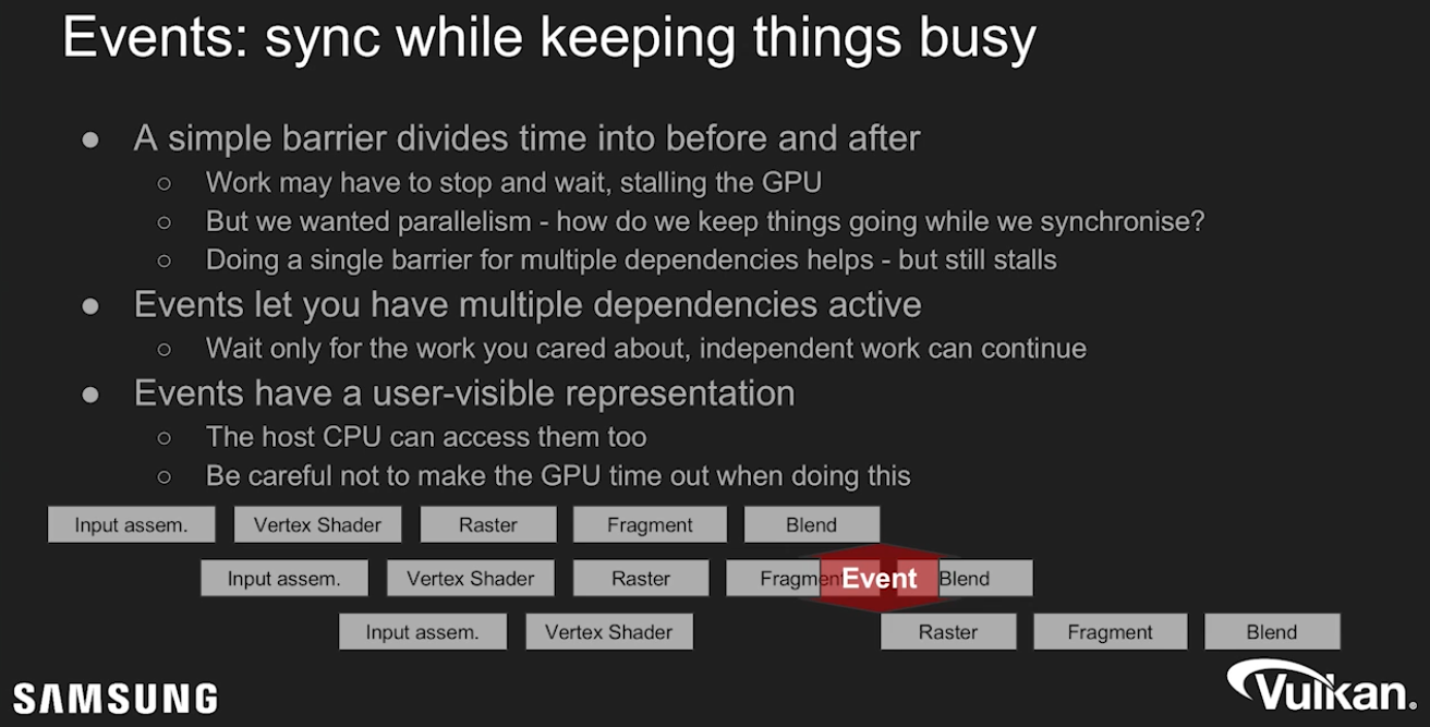 .
.
Semaphores and Fences
-
These objects are signaled as part of a
vkQueueSubmit. -
To signal a semaphore or fence, all previously submitted commands to the queue must complete.
-
If this were a regular pipeline barrier, we would have
srcStageMask = ALL_COMMANDS. However, we also get a full memory barrier, in the sense that all pending writes are made available. Essentially,srcAccessMask = MEMORY_WRITE. -
Signaling a fence or semaphore works like a full cache flush. Submitting commands to the Vulkan queue makes all memory access performed by host visible to all stages and access masks. Basically, submitting a batch issues a cache invalidation on host visible memory.
-
A common mistake is to think that you need to do this invalidation manually when the CPU is writing into staging buffers or similar:
-
srcStageMask = HOST -
dstStageMask = TRANSFER -
srcAccessMask = HOST_WRITE -
dstAccessMask = TRANSFER_READ -
If the write happened before
vkQueueSubmit, this is automatically done for you. -
This kind of barrier is necessary if you are using
vkCmdWaitEventswhere you wait for host to signal the event withvkSetEvent. In that case, you might be writing the necessary host data aftervkQueueSubmitwas called, which means you need a pipeline barrier like this. This is not exactly a common use case, but it’s important to understand when these API constructs are useful.
-
Semaphore
-
VkSemaphore -
Semaphores facilitate GPU <-> GPU synchronization across Vulkan queues.
-
Used for syncing multiple command buffer submissions one after other.
-
The CPU continues running without blocking.
-
-
Implicit memory guarantees when waiting for a Semaphore :
-
While signalling a semaphore makes all memory available , waiting for a semaphore makes memory visible .
-
This basically means you do not need a memory barrier if you use synchronization with semaphores since signal/wait pairs of semaphores works like a full memory barrier.
-
Example :
-
Queue 1 writes to an SSBO in compute, and consumes that buffer as a UBO in a fragment shader in queue 2.
-
We’re going to assume the buffer was created with
QUEUE_FAMILY_CONCURRENT. -
Queue 1
-
vkCmdDispatch -
vkQueueSubmit(signal = my_semaphore) -
There is no pipeline barrier needed here.
-
Signalling the semaphore waits for all commands, and all writes in the dispatch are made available to the device before the semaphore is actually signaled.
-
-
Queue 2
-
vkCmdBeginRenderPass -
vkCmdDraw -
vkCmdEndRenderPass -
vkQueueSubmit(wait = my_semaphore, pDstWaitStageMask = FRAGMENT_SHADER) -
When we wait for the semaphore, we specify which stages should wait for this semaphore, in this case the
FRAGMENT_SHADERstage. -
All relevant memory access is automatically made visible , so we can safely access
UNIFORM_READinFRAGMENT_SHADERstage, without having extra barriers. -
The semaphores take care of this automatically, nice!
-
-
-
-
Examples :
-
Basic signaling / waiting :
-
Let’s say we have semaphore S and queue operations A and B that we want to execute in order.
-
What we tell Vulkan is that operation A will 'signal' semaphore S when it finishes executing, and operation B will 'wait' on semaphore S before it begins executing.
-
When operation A finishes, semaphore S will be signaled, while operation B wont start until S is signaled.
-
After operation B begins executing, semaphore S is automatically reset back to being unsignaled, allowing it to be used again.
-
-
Image Transition on Swapchain Images :
-
We need to wait for the image to be acquired, and only then can we perform a layout transition.
-
The best way to do this is to use
pDstWaitStageMask = COLOR_ATTACHMENT_OUTPUT, and then usesrcStageMask = COLOR_ATTACHMENT_OUTPUTin a pipeline barrier which transitions the swapchain image after semaphore is signaled.
-
-
-
Types of Semaphores :
-
Binary Semaphores :
-
A binary semaphore is either unsignaled or signaled.
-
It begins life as unsignaled.
-
The way we use a binary semaphore to order queue operations is by providing the same semaphore as a 'signal' semaphore in one queue operation and as a 'wait' semaphore in another queue operation.
-
Only binary semaphores will be used in this tutorial, further mention of the term semaphore exclusively refers to binary semaphores.
-
-
Timeline Semaphores :
-
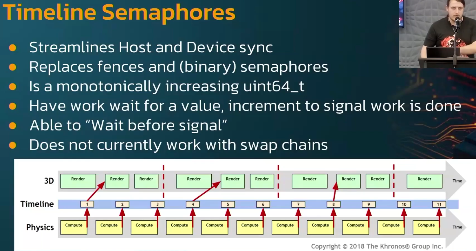 .
.
-
-
-
Correctly using the Semaphore for
vkQueuePresent:-
Since Vulkan SDK 1.4.313 , the validation layer reports cases where the present wait semaphore is not used safely:
-
This is currently reported as
VUID-vkQueueSubmit-pSignalSemaphores-00067or you may see "your VkSemaphore is being signaled by VkQueue, but it may still be in use by VkSwapchainKHR"
-
-
In this context, safely means that the Vulkan specification guarantees the semaphore is no longer in use and can be reused.
-
The problem :
-
vkQueuePresentKHRis different from thevkQueueSubmitfamily of functions in that it does not provide a way to signal a semaphore or a fence (without additional extensions). -
This means there is no way to wait for the presentation signal directly. It also means we don’t know whether
VkPresentInfoKHR::pWaitSemaphoresare still in use by the presentation operation. -
If
vkQueuePresentKHRcould signal, then waiting on that signal would confirm that the present queue operation has finished — including the wait onVkPresentInfoKHR::pWaitSemaphores. -
In summary, it’s not obvious when it’s safe to reuse present wait semaphores.
-
The Vulkan specification does not guarantee that waiting on a
vkQueueSubmitfence also synchronizes presentation operations.
-
-
The reuse of presentation resources should rely on
vkAcquireNextImageKHRor additional extensions, rather than onvkQueueSubmitfences. -
Solution options :
-
Allocate one "submit finished" semaphore per swapchain image instead of per in-flight frame.
-
Allocate the
submit_semaphoresarray based on the number of swapchain images (instead of the number of in-flight frames) -
Index this array using the acquired swapchain image index (instead of the current in-flight frame index)
-
-
Using
EXT_swapchain_maintenance1.-
See Vulkan#Recreating , for use with the swapchain.
-
-
Fences
-
VkFence -
Fences facilitate GPU -> CPU synchronization.
-
Used to know if a command buffer has finished being executed on the GPU.
-
-
While signalling a fence makes all memory available, it does not make them available to the CPU, just within the device. This is where
dstStageMask = PIPELINE_STAGE_HOSTanddstAccessMask = ACCESS_HOST_READflags come in. If you intend to read back data to the CPU, you must issue a pipeline barrier which makes memory available to the HOST as well. -
In our mental model, we can think of this as flushing the GPU L2 cache out to GPU main memory, so that CPU can access it over some bus interface.
-
In order to signal that fence, any pending writes to that memory must have been made available, so even recycled memory can be safely reused without a memory barrier. This point is kind of subtle, but it really helps your sanity not having to inject memory barriers everywhere.
-
Usage :
-
Similar to semaphores, fences are either in a signaled or unsignaled state.
-
Whenever we submit work to execute, we can attach a fence to that work. When the work is finished, the fence will be signaled.
-
Then we can make the CPU wait for the fence to be signaled, guaranteeing that the work has finished before the CPU continues.
-
Fences must be reset manually to put them back into the unsignaled state.
-
This is because fences are used to control the execution of the CPU, and so the CPU gets to decide when to reset the fence.
-
Contrast this to semaphores which are used to order work on the GPU without the CPU being involved.
-
-
Unlike the semaphore, the fence does block CPU execution.
-
In general, it is preferable to not block the host unless necessary.
-
We want to feed the GPU and the host with useful work to do. Waiting on fences to signal is not useful work.
-
Thus, we prefer semaphores, or other synchronization primitives not yet covered, to synchronize our work.
-
-
-
Example :
-
Taking a screenshot :
-
Once we have already done the necessary work on the GPU, we now need to transfer the image from the GPU over to the host and then save the memory to a file.
-
We have command buffer A which executes the transfer and fence F. We submit command buffer A with fence F, then immediately tell the host to wait for F to signal. This causes the host to block until command buffer A finishes execution.
-
Thus, we are safe to let the host save the file to disk, as the memory transfer has completed.
-
Unlike the semaphore example, this example does block host execution. This means the host won’t do anything except wait until the execution has finished. For this case, we had to make sure the transfer was complete before we could save the screenshot to disk.
-
-
Main Loop Synchronization
-
-
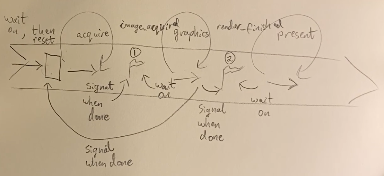 .
.
-
-
The entire video is just drawings.
-
-
-
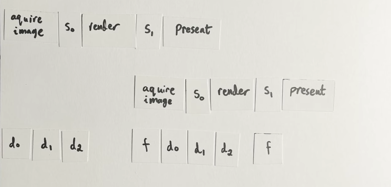 .
.
-
-
Good illustration.
-
The rest of the video is just code.
-
Does not comment on Multiple Frames In Flight.
-
-
Command Buffers
-
Commands in Vulkan, like drawing operations and memory transfers, are not executed directly using function calls. You have to record all the operations you want to perform in command buffer objects.
-
The advantage of this is that when we are ready to tell Vulkan what we want to do, all the commands are submitted together. Vulkan can more efficiently process the commands since all of them are available together.
-
In addition, this allows command recording to happen in multiple threads if so desired.
Command Pools
-
Create and allocate Command Buffers.
-
Command pools are opaque objects that command buffer memory is allocated from, and which allow the implementation to amortize the cost of resource creation across multiple command buffers.
Creation
-
-
device-
Is the logical device that creates the command pool.
-
-
pAllocator-
Controls host memory allocation as described in the Memory Allocation chapter.
-
-
pCommandPool-
Is a pointer to a VkCommandPool handle in which the created pool is returned.
-
-
pCreateInfo-
queueFamilyIndex-
Designates a queue family as described in section Queue Family Properties . All command buffers allocated from this command pool must be submitted on queues from the same queue family.
-
Command buffers are executed by submitting them on one of the device queues (graphics and presentation queues, for example).
-
Each command pool can only allocate command buffers that are submitted on a single type of queue.
-
-
flags-
Is a bitmask indicating usage behavior for the pool and command buffers allocated from it.
-
COMMAND_POOL_CREATE_TRANSIENT-
Hint that command buffers are rerecorded with new commands very often (may change memory allocation behavior)
-
-
COMMAND_POOL_CREATE_RESET_COMMAND_BUFFER-
Allow command buffers to be rerecorded individually, without this flag they all have to be reset together
-
If we record a command buffer every frame, we want to be able to reset and rerecord over it, thus, this flag should be enabled so a command buffer can be reset individually.
-
-
COMMAND_POOL_CREATE_PROTECTED-
Specifies that command buffers allocated from the pool are protected command buffers.
-
-
-
Management
-
Manages the memory that is used to store the buffers and command buffers are allocated from them.
-
Destroying a Command Pool, destroys the Command Buffers associated.
-
Reset the whole Command Pool :
-
-
Resetting a command pool recycles all of the resources from all of the command buffers allocated from the command pool back to the command pool. All command buffers that have been allocated from the command pool are put in the initial state .
-
Any primary command buffer allocated from another VkCommandPool that is in the recording or executable state and has a secondary command buffer allocated from
commandPoolrecorded into it, becomes invalid .
-
-
-
Free individual Command Buffers :
-
-
device-
Is the logical device that owns the command pool.
-
-
commandPool-
Is the command pool from which the command buffers were allocated.
-
-
commandBufferCount-
Is the length of the
pCommandBuffersarray.
-
-
pCommandBuffers-
Is a pointer to an array of handles of command buffers to free.
-
-
Any primary command buffer that is in the recording or executable state and has any element of
pCommandBuffersrecorded into it, becomes invalid .
-
-
Command Buffer
Creation / Allocation
-
-
Encodes GPU commands.
-
All execution that is performed on the GPU itself (not in the driver) has to be encoded in a command buffer.
-
-
-
pAllocateInfo-
commandPool-
Is the command pool from which the command buffers are allocated.
-
-
level-
Specifies if the allocated command buffers are primary or secondary command buffers.
-
`COMMAND_BUFFER_LEVEL_PRIMARY
-
Command Buffer Primary.
-
-
`COMMAND_BUFFER_LEVEL_SECONDARY
-
Command Buffer Secondary.
-
-
commandBufferCount-
Is the number of command buffers to allocate from the pool.
-
-
pCommandBuffers-
Is a pointer to an array of Command Buffer handles in which the resulting command buffer objects are returned. The array must be at least the length specified by the
commandBufferCountmember ofpAllocateInfo. Each allocated command buffer begins in the initial state.
-
-
Lifecycle
-
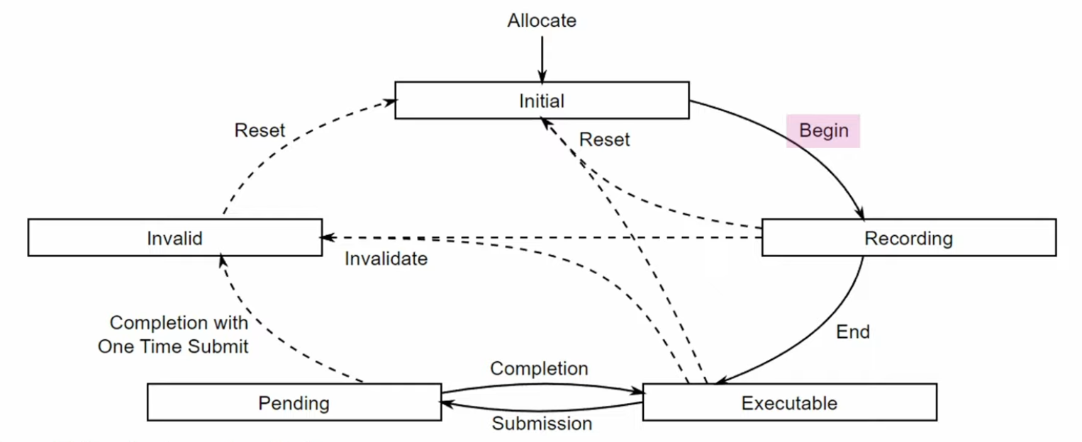 .
.
-
Reset an single Command Buffer :
-
Once a command buffer has been submitted, it’s still “alive”, and being consumed by the GPU, at this point it is NOT safe to reset the command buffer yet. You need to make sure that the GPU has finished executing all of the commands from that command buffer until you can reset and reuse it.
-
-
commandBuffer-
Is the command buffer to reset. The command buffer can be in any state other than pending , and is moved into the initial state .
-
-
flags-
Is a bitmask of VkCommandBufferResetFlagBits controlling the reset operation.
-
-
Any primary command buffer that is in the recording or executable state and has
commandBufferrecorded into it, becomes invalid . -
After a command buffer is reset, any objects or memory specified by commands recorded into the command buffer must no longer be accessed when the command buffer is accessed by the implementation.
-
-
If the command buffer was already recorded once, then a call to it will implicitly reset it.
-
Levels
-
Primary :
-
Only these can be submitted to queues for execution.
-
Cannot be called from other command buffers.
-
-
Secondary :
-
Cannot be submitted directly, but can be called from primary command buffers.
-
"We won’t make use of the secondary command buffer functionality here, but you can imagine that it’s helpful to reuse common operations from primary command buffers."
-
-
A primary command buffer would use this to execute a secondary command buffer.
-
-
Re-recording :
-
If a secondary moves to the invalid state or the initial state, then all primary buffers it is recorded in move to the invalid state. A primary moving to any other state does not affect the state of a secondary recorded in it.
-
So, when a secondary command is re-recorded, the primary becomes invalid.
-
Eve: "It is not capturing a reference to a command buffer, it is going through and copying all the commands in the command buffer into itself."
-
-
Command Types
-
Action-Type, State-Type, Sync-Type.
-
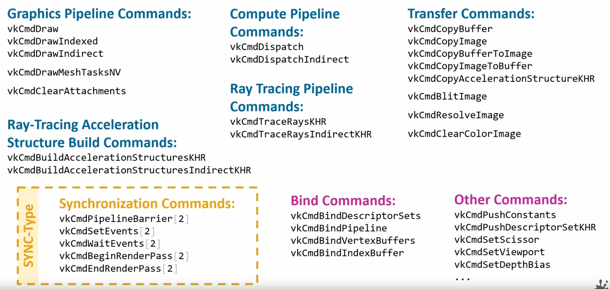 .
.
Command Buffer Recording
-
Writes the commands we want to execute into a command buffer.
-
It’s not possible to append commands to a buffer at a later time.
-
-
commandBuffer-
Is the handle of the command buffer which is to be put in the recording state.
-
-
pBeginInfo-
Specifies some details about the usage of this specific command buffer.
-
flags-
Specifies how we’re going to use the command buffer.
-
COMMAND_BUFFER_USAGE_ONE_TIME_SUBMIT-
The command buffer will be rerecorded right after executing it once.
-
-
COMMAND_BUFFER_USAGE_RENDER_PASS_CONTINUE-
This is a secondary command buffer that will be entirely within a single render pass.
-
-
COMMAND_BUFFER_USAGE_SIMULTANEOUS_USE-
The command buffer can be resubmitted while it is also already pending execution.
-
-
None of these flags are applicable for us right now.
-
pInheritanceInfo-
VkCommandBufferInheritanceInfo.-
If the command buffer is a secondary command buffer, then the
VkCommandBufferInheritanceInfostructure defines any state that will be inherited from the primary command buffer:
-
-
Used if
commandBufferis a secondary command buffer. If this is a primary command buffer, then this value is ignored. -
It specifies which state to inherit from the calling primary command buffers.
-
-
-
-
The command buffer must have been in the recording state , and, if successful, is moved to the executable state .
-
If there was an error during recording, the application will be notified by an unsuccessful return code returned by
vkEndCommandBuffer, and the command buffer will be moved to the invalid state .
-
Pre-recording
-
"Many early Vulkan tutorials and documents recommended writing a command buffer once and re-using it wherever possible. In practice however re-use rarely has the advertized performance benefit while incurring a non-trivial development burden due to the complexity of implementation. While it may appear counterintuitive, as re-using computed data is a common optimization, managing a scene with objects being added and removed as well as techniques such as frustum culling which vary the draw calls issued on a per frame basis make reusing command buffers a serious design challenge. It requires a caching scheme to manage command buffers and maintaining state for determining if and when re-recording becomes necessary. Instead, prefer to re-record fresh command buffers every frame. If performance is a problem, recording can be multithreaded as well as using secondary command buffers for non-variable draw calls, like post processing."
-
Source .
-
Multi-threading Recording
-
Usage of secondary command buffers for Vulkan Multithreaded Recording .
-
Usage of secondary command buffers for Vulkan Multithreaded Recording .
-
There's a example code section.
-
-
External synchronization
-
A type of synchronization required of the application, where parameters defined to be externally synchronized must not be used simultaneously in multiple threads.
-
-
Internal Synchronization
-
A type of synchronization required of the implementation, where parameters not defined to be externally synchronized may require internal mutexing to avoid multithreaded race conditions.
-
-
Any object parameters that are not labeled as externally synchronized are either not mutated by the command or are internally synchronized.
-
Additionally, certain objects related to a command’s parameters (e.g. command pools and descriptor pools) may be affected by a command, and must also be externally synchronized.
Queues
-
Only a single thread can be submitting to a given queue at any time. If you want multiple threads doing
VkQueueSubmit, then you need to create multiple queues. -
As the number of queues can be as low as 1 in some devices, what engines tend to do for this is to do something similar to the pipeline compile thread or the OpenGL api call thread, and have a thread dedicated to just doing
VkQueueSubmit. -
As
VkQueueSubmitis a very expensive operation, this can bring a very nice speedup as the time spent executing that call is done in a second thread and the main logic of the engine doesn’t have to stop. -
Data upload is another section that is very often multithreaded. In here, you have a dedicated IO thread that will load assets to disk, and said IO thread will have its own queue and command allocators, hopefully a transfer queue. This way it is possible to upload assets at a speed completely separated from the main frame loop, so if it takes half a second to upload a set of big textures, you don’t have a hitch. To do that, you need to create a transfer or async-compute queue (if available), and dedicate that one to the loader thread. Once you have that, it’s similar to what was commented on the pipeline compiler thread, and you have an IO thread that communicates through a parallel queue with the main simulation loop to upload data in an asynchronous way. Once a transfer has been uploaded, and checked that it has finished with a Fence, then the IO thread can send the info to the main loop, and then the engine can connect the new textures or models into the renderer.
Command Pools
-
When you record command buffers, their command pools can only be used from one thread at a time. While you can create multiple command buffers from a command pool, you cant fill those commands from multiple threads. If you want to record command buffers from multiple threads, then you will need more command pools, one per thread.
-
Secondary Command Buffers :
-
Vulkan command buffers have a system for primary and secondary command buffers. The primary buffers are the ones that open and close RenderPasses, and can get directly submitted to a queue. Secondary command buffers are used as “child” command buffers that execute as part of a primary one.
-
Their main purpose is multithreading.
-
Secondary command buffers cant be submitted into a queue on their own.
-
-
Command Pools are a system to allow recording command buffers across multiple threads.
-
They enable different threads to use different allocators, without internal synchronization on each use.
-
-
A single command pool must be externally synchronized ; it must not be accessed simultaneously from multiple threads.
-
That includes use via recording commands on any command buffers allocated from the pool, as well as operations that allocate, free, and reset command buffers or the pool itself.
-
-
If you want multithreaded command recording, you need more
VkCommandPoolobjects. By using a separate command pool in each host-thread the application can create multiple command buffers in parallel without any costly locks.-
For that reason, we will pair a command buffer with its command allocator.
-
-
You can allocate as many
VkCommandBufferas you want from a given pool, but you can only record commands from one thread at a time. -
Command buffers can be recorded on multiple threads while having a relatively light thread handle the submissions.
-
If two commands access the same object or memory and at least one of the commands declares the object to be externally synchronized, then the caller must guarantee not only that the commands do not execute simultaneously, but also that the two commands are separated by an appropriate memory barrier (if needed).
-
Similarly, if a Vulkan command accesses a non-const memory parameter and the application also accesses that memory, or if the application writes to that memory and the command accesses it as a const memory parameter, the application must ensure the accesses are properly synchronized with a memory barrier if needed.
-
Memory barriers are particularly relevant for hosts based on the ARM CPU architecture, which is more weakly ordered than many developers are accustomed to from x86/x64 programming. Fortunately, most higher-level synchronization primitives (like the pthread library) perform memory barriers as a part of mutual exclusion, so mutexing Vulkan objects via these primitives will have the desired effect.
Pipelines
-
In Vulkan, to execute code on the GPU, we need to set up a pipeline.
-
There are two types of pipelines, Graphics and Compute:
-
Compute pipelines :
-
Are much simpler, because they only require the data for the shader code, and the layout for the descriptors used for data bindings.
-
-
Graphics pipelines :
-
Have to configure a considerable amount of state for all of the fixed-function hardware in the GPU such as color blending, depth testing, or geometry formats.
-
-
-
Both types of pipelines share the shader modules and the layouts, which are built in the same way.
-
VkPipeline
Pipeline Layout
-
A collection of
DescriptorSetLayoutsandPushConstantRangedefining its push constant usage. -
PipelineLayouts for a graphics and compute pipeline are made in the same way, and they must be created before the pipeline itself.
-
-
-
Structure specifying the parameters of a newly created pipeline layout object
-
setLayoutCount-
Is the number of descriptor sets included in the pipeline layout.
-
-
pSetLayouts-
Is a pointer to an array of
VkDescriptorSetLayoutobjects. -
The implementation must not access these objects outside of the duration of the command this structure is passed to.
-
-
-
-
pCreateInfo-
Is a pointer to a VkPipelineLayoutCreateInfo structure specifying the state of the pipeline layout object.
-
-
flags-
Is a bitmask of VkPipelineLayoutCreateFlagBits specifying options for pipeline layout creation.
-
-
setLayoutCount-
See Vulkan#Descriptor Set Layout for more information.
-
Is the number of descriptor sets included in the pipeline layout.
-
-
pSetLayouts-
Is a pointer to an array of
VkDescriptorSetLayoutobjects. The implementation must not access these objects outside of the duration of the command this structure is passed to.
-
-
pushConstantRangeCount-
Is the number of push constant ranges included in the pipeline layout.
-
-
pPushConstantRanges-
Is a pointer to an array of VkPushConstantRange structures defining a set of push constant ranges for use in a single pipeline layout. In addition to descriptor set layouts, a pipeline layout also describes how many push constants can be accessed by each stage of the pipeline.
-
-
-
Mesh Shaders
Support
-
(2025-09-12)
-
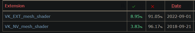 .
.
-
It is important to note that while portability between APIs can be achieved, portability in performance among vendors is much harder. This is one of the reasons why this extension has not been released as a ratified KHR extension and Khronos continues to investigate improvements to geometry rasterization.
-
There are further aspects that can influence the performance of mesh shaders in a vendor dependent way:
-
The number of maximum output vertices and primitives that a mesh shader is compiled with.
-
The number of per-vertex and per-primitive output attributes that are passed to fragment shaders. For example, it may be beneficial to fetch additional attributes in the fragment shader and interpolate them via hardware barycentrics to reduce the output space of the mesh shader.
-
The complexity of the culling performed in the mesh shader. For example details regarding the per-vertex and/or per-primitive culling with compact outputs compared to letting the hardware perform culling.
-
The usage of additional shared memory. If possible developers should use subgroup operations (such as shuffle) instead.
-
The task payload size.
-
Task shaders may add overhead, use them only when they can cull a meaningful number of primitives or when actual geometry amplification is desired.
-
Do not try to reimplement the fixed-function pipeline, strive for simpler algorithms instead.
-
-
 .
.
Motivation
-
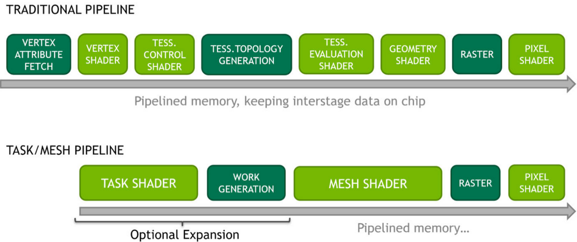 .
.
-
 .
.
-
The current state of the Graphics Pipeline is not a direct mapping of how a GPU operates.
-
There's a lot of Per Vertex -> Per Primitive -> Per Vertex -> Per Primitive happening inside a Graphics Pipeline.
-
The idea is to use the flexibility of Compute Shaders and use the GPU more closely as it operates.
-
Mesh and Task shaders follow the compute programming model and use threads cooperatively to generate meshes within a workgroup. The vertex and index data for these meshes are written similarly to shared memory in compute shaders.
-
Mesh shader output is directly consumed by the rasterizer, as opposed to the previous approach of using a compute dispatch followed by an indirect draw.
-
Mesh Shading applications can avoid preallocation of output buffers.
-
Before deciding to use mesh shaders, developers should ensure they are a good fit for their application. The traditional pipeline may still be best suited to many use cases, and it may not be trivial to improve performance using the mesh shading pipeline given the long evolution and optimization efforts applied to the traditional pipeline stages.
-
Applications and games dealing with high geometric complexity can, however, benefit from the flexibility of the two-stage approach, which allows efficient culling , level-of-detail techniques as well as procedural generation .
-
Compared to the traditional pipeline, the mesh shaders allow easy access to the topology of the generated primitives and developers are free to repurpose the threads to do both vertex shading and primitive shading work. This is in contrast to tessellation shaders, which, while fast, provide very limited control over the triangles created, and geometry shaders, which use a single-thread programming model that is inefficient for modern streaming processors.
Task Shader
-
Is optional and provides a way to implement geometry amplification by creating variable mesh shader workgroups directly in the pipeline. Task shader workgroups can output an optional payload, which is visible as read-only input to all its child mesh shader workgroups.
-
A Task Shader decides how many Mesh Shaders you would like to run.
Meshlets / Triangle Clusters
-
 .
.
-
When rasterizing geometry, mesh shaders typically make use of pre-computed triangle clusters of an upper bound in the number of vertices and triangles, also sometimes referred to as meshlets. Because task and mesh shaders, like compute, have only workgroup and invocation indices as input, all data fetching is handled by the application directly, which entirely removes fixed-function vertex processing and input assembly. This allows developers to be flexible in the storage of mesh data in both vertex and primitive topology representations. Another very common technique is to leverage the task shader and let one local invocation test one cluster for visibility. Through the use of subgroup operations developers can compute and write out information about the visible clusters into the task shader payload.
-
The meshlet / primitive cluster dimensions can have an especially big impact for the developer, as when streaming it is ideal to store assets with a fixed clustering in advance. Vendors may have different performance recommendations and so we suggest the use of smaller cluster sizes that work equally well across multiple vendors and process multiple small clusters at once on implementations that perform better with larger clusters. In this area we advise developers to experiment and consult with their hardware vendors for recommendations.
Using it
-
-
The URL comes from
NV_mesh_shader; maybe it's relevant?
-
-
-
This OpenGL/Vulkan sample illustrates the use of "mesh shaders" for rendering CAD models.
-
-
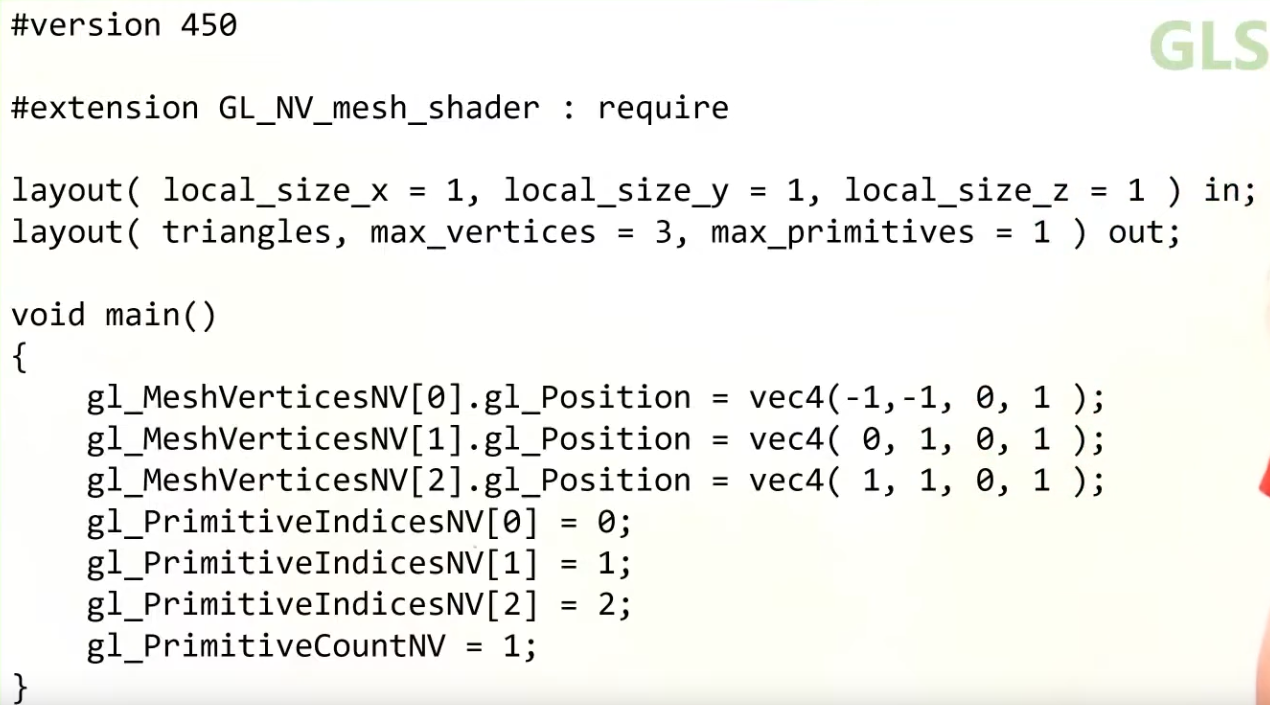 .
.
-
The recommended idea is a Mesh Shader to operate on a Meshlet.
What a Mesh Shader enables
-
You can do very early culling.
-
It can be faster than the classical Graphics Pipeline, if correctly optimized.
-
Mesh Shader output Execution Mode :
-
The mesh stage will set either
OutputPoints,OutputLinesEXT, orOutputTrianglesEXT
#extension GL_EXT_mesh_shader : require // Only 1 of the 3 is allowed layout(points) out; layout(lines) out; layout(triangles) out; -
Cluster Culling Shader
-
-
HUAWEI_cluster_culling_shader.
-
Graphics Pipeline
-
The graphics pipeline is required for all common drawing operations.
-
Holds the state of the GPU needed to draw. For example: shaders, rasterization options, depth settings.
-
It describes the configurable state of the graphics card, like the viewport size and depth buffer operation and the programmable state using VkShaderModule objects.
Stages
-
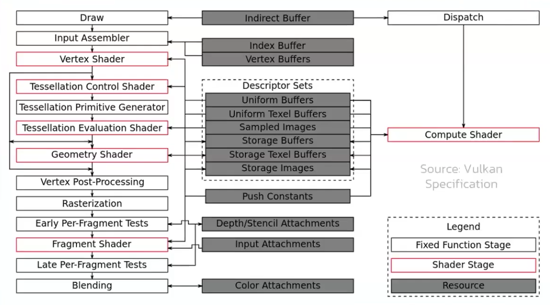 .
.
-
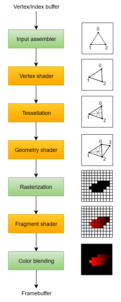 .
.
-
Disabling stages :
-
The tessellation and geometry stages can be disabled if you are just drawing simple geometry.
-
If you are only interested in depth values, then you can disable the fragment shader stage, which is useful for shadow map generation.
-
-
Fixed-function stages :
-
Allow you to tweak their operations using parameters, but the way they work is predefined.
-
Dynamic State :
-
While most of the pipeline state needs to be baked into the pipeline state, a limited amount of the state can actually be changed without recreating the pipeline at draw time.
-
Examples are the size of the viewport, line width and blend constants.
-
If you want to use dynamic state and keep these properties out, then you’ll have to fill in a
VkPipelineDynamicStateCreateInfostruct. -
This will cause the configuration of these values to be ignored , and you will be able (and required) to specify the data at drawing time.
-
This results in a more flexible setup and is widespread for things like viewport and scissor state, which would result in a more complex setup when being baked into the pipeline state.
-
-
-
Programmable stages :
-
Means that you can upload your own code to the graphics card to apply exactly the operations you want.
-
This allows you to use fragment shaders, for example, to implement anything from texturing and lighting to ray tracers. These programs run on many GPU cores simultaneously to process many objects, like vertices and fragments in parallel.
-
-
Immutability :
-
Is almost completely immutable, so you must recreate the pipeline from scratch if you want to change shaders, bind different framebuffers or change the blend function.
-
The disadvantage is that you’ll have to create a number of pipelines (many VkPipeline objects) that represent all the different combinations of states you want to use in your rendering operations. However, because all the operations you’ll be doing in the pipeline are known in advance, the driver can optimize for it much better.
-
Runtime performance is more predictable because large state changes like switching to a different graphics pipeline are made very explicit.
-
-
Only some basic configuration, like viewport size and clear color, can be changed dynamically.
-
Shader Compilation
Shader Module
-
A
VkShaderModuleis a processed shader file. -
We create it from a pre-compiled SPIR-V file.
-
We can call
vkDestroyShaderModuleafter they are used for the graphics pipeline creation.
Input Assembly
-
Fixed-function stage.
-
Collects the raw vertex data from the buffers you specify and may also use an index buffer to repeat certain elements without having to duplicate the vertex data itself.
-
VkPipelineVertexInputStateCreateInfo-
Describes the format of the vertex data that will be passed to the vertex shader.
-
pVertexBindingDescriptions-
Spacing between data and whether the data is per-vertex or per-instance (see instancing ).
-
-
pVertexAttributeDescriptions-
Type of the attributes passed to the vertex shader, which binding to load them from and at which offset.
-
-
-
VkPipelineInputAssemblyStateCreateInfo.-
Describes two things: what kind of geometry will be drawn from the vertices and if primitive restart should be enabled.
-
topology-
PRIMITIVE_TOPOLOGY_POINT_LIST-
points from vertices
-
-
PRIMITIVE_TOPOLOGY_LINE_LIST-
line from every two vertices without reuse
-
-
PRIMITIVE_TOPOLOGY_LINE_STRIP-
the end vertex of every line is used as start vertex for the next line
-
-
PRIMITIVE_TOPOLOGY_TRIANGLE_LIST-
triangle from every three vertices without reuse
-
-
PRIMITIVE_TOPOLOGY_TRIANGLE_STRIP-
the second and third vertex of every triangle is used as first two vertices of the next triangle
-
-
-
primitiveRestartEnable-
Normally, the vertices are loaded from the vertex buffer by index in sequential order, but with an element buffer you can specify the indices to use yourself.
-
This allows you to perform optimizations like reusing vertices.
-
-
If you set this to
TRUE, then it’s possible to break up lines and triangles in the_STRIPtopology modes by using a special index of0xFFFFor0xFFFFFFFF.
-
-
Primitive Topology
-
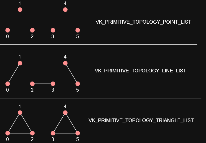 .
.
Vertex Shader
-
Programmable stage.
-
Is run for every vertex and generally applies transformations to turn vertex positions from model space to screen space. It also passes per-vertex data down the pipeline.
-
The
VkShaderModuleobjects are created from shader byte code. -
Accesses and computes one vertex at a time.
Tessellation Shader
-
Is run for every vertex and generally applies transformations to turn vertex positions from model space to screen space. It also passes per-vertex data down the pipeline.
-
You can do tessellation in the Geometry Shader, but the Tessellation Shader is more appropriate and efficient.
-
 .
.
-
Sending this amount of vertices to the Vertex Shader would be quite more expensive than generating them in the Tessellation Shader.
-
-
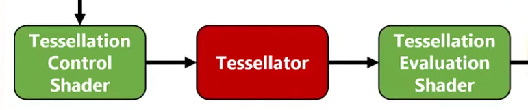 .
.
-
Tessellation Evaluation Shader.
-
Kinda like a Vertex Shader, after the Tessellation.
-
-
-
I was too lazy to watch it all.
-
The inputs are complicated, etc.
-
-
Tessellation output Execution Mode :
-
The tessellation evaluation stage will set either
Triangles,Quads, orIsolines
// Only 1 of the 3 is allowed layout(quads) in; layout(isolines) in; layout(triangles) in; -
Geometry Shader
-
Programmable stage.
-
It operates on primitives .
-
Is run on every primitive (triangle, line, point) and can discard it or output more primitives than came in. This is similar to the tessellation shader but much more flexible.
-
However, it is used little in today’s applications because the performance is not that good on most graphics cards except for Intel’s integrated GPUs.
-
Also, almost all geometry shader use cases can be replaced with a more modern Mesh shader pipeline, which like ray tracing is a wholly new pipeline solution, so it exists outside the standard graphics pipeline setup.
-
-
 .
.
-
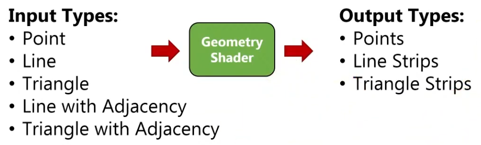
-
A Vertex Shader is more parallelized than a Geometry Shader.
-
A Vertex Shader computes one vertex at a time, while a geometry shader gets all the vertices that compose a primitive .
-
It does not have access to the whole mesh, just the vertices that compose the current primitive.
-
-
OpenGL Primitives :
-
May be useful.
-
 .
.
-
 .
.
-
-
Think of the Primitive Inputs as just the amount of vertices you are sending at a time.
-
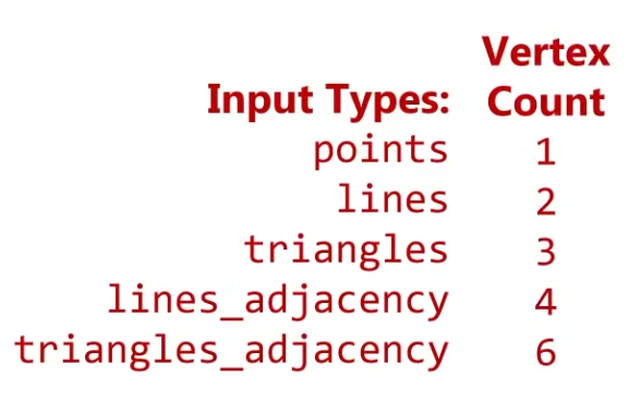 .
.
-
The reason for this is that you can get any primitive input and have any primitive output.
-
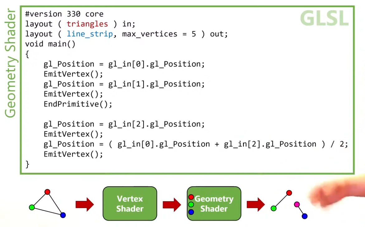 .
.
-
Use
EndPrimitive()so the line strips are separated.
-
-
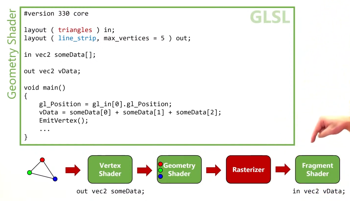 .
.
-
The Vertex Shader can output data to the Geometry Shader, in the form of an array.
-
The Geometry Shader can output data to the Fragment Shader, in a form of an interpolated value, using barycentric coordinates.
-
-
Instancing :
-
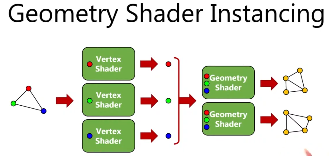 .
.
-
You can have many instances of a Geometry Shader, where the input is the same but the output changes.
-
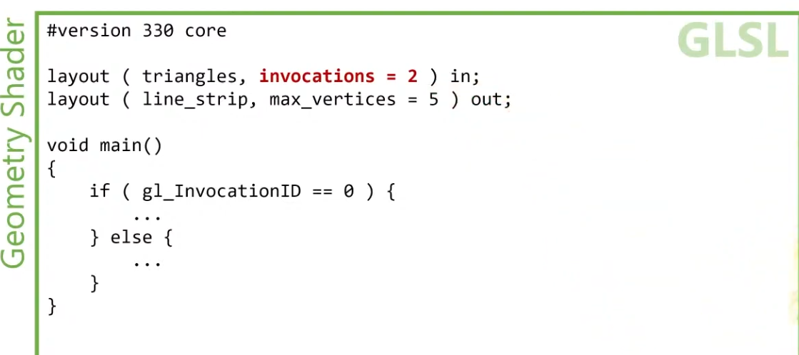 .
.
-
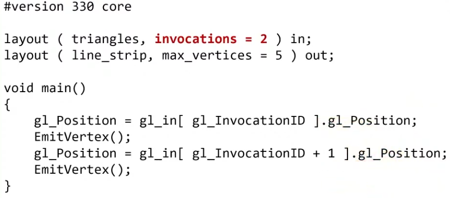 .
.
-
-
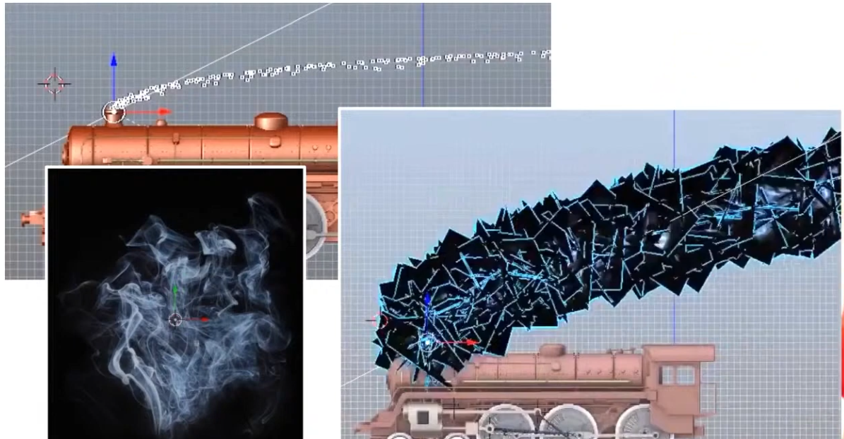 .
.
-
The smoke is a quad facing the camera (billboard).
-
The points are converted to quads.
-
-
 .
.
-
 .
.
-
Geometry output Execution Mode :
-
A geometry stage will set either
OutputPoints,OutputLineStrip, orOutputTriangleStrip
// Only 1 of the 3 is allowed layout(points) out; layout(line_strip) out; layout(triangle_strip) out; -
Rasterization
-
Fixed-function stage.
-
Breaks the primitives into fragments .
-
These are the pixel elements that they fill on the framebuffer.
-
Any fragments that fall outside the screen are discarded, and the attributes outputted by the vertex shader are interpolated across the fragments.
-
Fragments that are behind other primitive fragments can also be discarded here because of depth testing.
-
VkPipelineRasterizationStateCreateInfo.-
polygonMode -
lineWidth-
Is the width of rasterized line segments.
-
The maximum line width that is supported depends on the hardware.
-
Any line thicker than
1.0frequires you to enable thewideLinesGPU feature. -
If set to
0.0f, you get:lineWidthis 0.0, but the line width state is static (pCreateInfos[0].pDynamicState->pDynamicStatesdoes not containDYNAMIC_STATE_LINE_WIDTH) andwideLinesfeature was not enabled. The Vulkan spec states: If the pipeline requires pre-rasterization shader state, and thewideLinesfeature is not enabled, and no element of thepDynamicStatesmember ofpDynamicStateisDYNAMIC_STATE_LINE_WIDTH, the lineWidth member of pRasterizationState must be 1.0. -
So, set it to
1.0fby default.
-
-
cullMode-
NONE-
Specifies that no triangles are discarded
-
-
FRONT-
Specifies that front-facing triangles are discarded
-
-
BACK-
Specifies that back-facing triangles are discarded
-
-
FRONT_AND_BACK-
Specifies that all triangles are discarded.
-
-
Following culling, fragments are produced for any triangles which have not been discarded.
-
-
frontFace-
Specifies the vertex order for the faces to be considered front-facing.
-
COUNTER_CLOCKWISE-
Specifies that a triangle with positive area is considered front-facing.
-
-
CLOCKWISE-
Specifies that a triangle with negative area is considered front-facing.
-
-
Any triangle which is not front-facing is back-facing, including zero-area triangles.
-
-
rasterizerDiscardEnable.-
When enabled, primitives are discarded after they are processed by the last active shader stage in the pipeline before rasterization.
-
Controls whether primitives are discarded immediately before the rasterization stage. This is important because when this is set to
TRUEthe rasterization hardware is not executed. -
There are many Validation Usage errors that will not occur if this is set to
TRUEbecause some topology hardware is unused and can be ignored. -
Enabling this state is meant for very specific use cases. Prior to compute shaders, this was a common technique for writting geometry shader output to a buffer.
-
It can be used to debug/profile non-rasterization bottlenecks.
-
-
flags-
Reserved for future use.
-
-
depthClampEnable-
See the Depth section for details.
-
-
depthBiasEnable-
See the Depth section for details.
-
-
depthBiasConstantFactor-
See the Depth section for details.
-
-
depthBiasSlopeFactor-
See the Depth section for details.
-
-
depthBiasClamp-
See the Depth section for details.
-
-
Polygon Mode
-
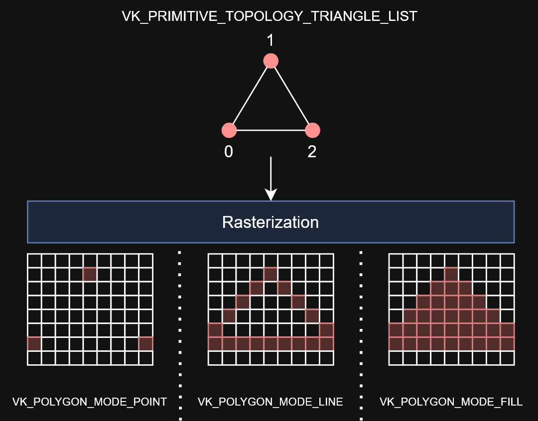 .
.
-
Determines how fragments are generated for geometry.
-
These modes affect only the final rasterization of polygons. The polygon’s vertices are shaded and the polygon is clipped and possibly culled before these modes are applied.
-
FILL-
Fill the area of the polygon with fragments.
-
-
LINE-
Polygon edges are drawn as lines
-
-
POINT-
Polygon vertices are drawn as points
-
If
VkPhysicalDeviceMaintenance5Properties::polygonModePointSizeisTRUE, the point size of the final rasterization of polygons is taken fromPointSize. -
Otherwise, the point size of the final rasterization of polygons is 1.0.
-
-
FILL_RECTANGLE_NV-
Specifies that polygons are rendered using polygon rasterization rules, modified to consider a sample within the primitive if the sample location is inside the axis-aligned bounding box of the triangle after projection.
-
Note that the barycentric weights used in attribute interpolation can extend outside the range
[0,1]when these primitives are shaded. -
Special treatment is given to a sample position on the boundary edge of the bounding box. In such a case, if two rectangles lie on either side of a common edge (with identical endpoints) on which a sample position lies, then exactly one of the triangles must produce a fragment that covers that sample during rasterization.
-
Polygons rendered in
FILL_RECTANGLE_NVmode may be clipped by the frustum or by user clip planes. If clipping is applied, the triangle is culled rather than clipped. -
Area calculation and facingness are determined for
FILL_RECTANGLE_NVmode using the triangle’s vertices.
-
-
If you have a vertex shader that has
PRIMITIVE_TOPOLOGY_TRIANGLE_LISTinput and then during rasterization usesPOLYGON_MODE_LINE, the effective topology is the Line Topology Class at that time. This means something likelineWidthwould be applied when filling in the polygon withPOLYGON_MODE_LINE.
Fragment Operations
Order
-
Discard rectangles test
-
Scissor test
-
Exclusive scissor test
-
Sample mask test
-
Certain Fragment shading operations:
-
Sample Mask Accesses
-
Tile Image Reads
-
Depth Replacement
-
Stencil Reference Replacement
-
Interlocked Operations
-
-
Multisample coverage
-
Depth bounds test
-
Stencil test
-
Depth test
-
Representative fragment test
-
Sample counting
-
Coverage to color
-
Coverage reduction
-
Coverage modulation
Early Per-Fragment Tests
-
OpenGL 4.6:
-
Once fragments are produced by rasterization, a number of per-fragment operations are performed prior to fragment shader execution. If a fragment is discarded during any of these operations, it will not be processed by any subsequent Stage, including fragment shader execution.
-
Three fragment operations are performed, and a further three are optionally performed on each fragment, in the following order:
-
the pixel ownership test (see section 14.9.1);
-
the scissor test (see section 14.9.2);
-
multisample fragment operations (see section 14.9.3);
-
-
If early per-fragment operations are enabled, these tests are also performed:
-
the stencil test (see section 17.3.3);
-
the depth buffer test (see section 17.3.4);
-
The depth buffer test discards the incoming fragment if a depth comparison fails. The comparison is enabled or disabled with the generic Enable and Disable commands using target DEPTH_TEST. When disabled, the depth comparison and subsequent possible updates to the depth buffer value are bypassed and the fragment is passed to the next operation. The stencil value, however, is modified as indicated below as if the depth buffer test passed. If enabled, the comparison takes place and the depth buffer and stencil value may subsequently be modified.
-
-
occlusion query sample counting (see section 17.3.5)
-
-
Early fragment tests, as an optimization, exist to prevent unnecessary executions of the Fragment Shader. If a fragment will be discarded based on the Depth Test (due perhaps to being behind other geometry), it saves performance to avoid executing the fragment shader. There is specialized hardware that makes this particularly efficient in many GPUs.
-
The most effective way to use early depth test hardware is to run a depth-only pre-processing pass. This means to render all available geometry, using minimal shaders and a rendering pipeline that only writes to the depth buffer. The Vertex Shader should do nothing more than transform positions, and the Fragment Shader does not even need to exist.
-
This provides the best performance gain if the fragment shader is expensive, or if you intend to use multiple passes across the geometry.
-
Limitations :
-
The Spec states that these operations happen after fragment processing. However, a specification only defines apparent behavior, so the implementation is only required to behave "as if" it happened afterwards.
-
Therefore, an implementation is free to apply early fragment tests if the Fragment Shader being used does not do anything that would impact the results of those tests. So if a fragment shader writes to glFragDepth, thus changing the fragment's depth value, then early testing cannot take place, since the test must use the new computed value.
-
Do recall that if a fragment shader writes to gl_FragDepth, even conditionally, it must write to it at least once on all codepaths.
-
There can be other hardware-based limitations as well. For example, some hardware will not execute an early depth test if the (deprecated) alpha test is active, as these use the same hardware on that platform. Because this is a hardware-based optimization, OpenGL has no direct controls that will tell you if early depth testing will happen.
-
Similarly, if the fragment shader discards the fragment with the discard keyword, this will almost always turn off early depth tests on some hardware. Note that even conditional use of discard will mean that the FS will turn off early depth tests.
-
All of the above limitations apply only to early testing as an optimization. They do not apply to anything below.
-
-
More recent hardware can force early depth tests, using a special fragment shader layout qualifier:
-
layout(early_fragment_tests).-
Vulkan:
-
Specifying is a way of the application programmer providing a promise to the implementation that it is algorithmically safe to kill the fragments, so you explicitly allow the change in application-visible behavior.
-
Specifying this will make per-fragment tests be performed before fragment shader execution. If this is not declared, per-fragment tests will be performed after fragment shader execution. Only one fragment shader (compilation unit) need declare this, though more than one can. If at least one declares this, then it is enabled.
-
-
OpenGL 4.6:
-
An explicit control is provided to allow fragment shaders to enable early fragment tests. If the fragment shader specifies the
early_fragment_testslayout qualifier, the per-fragment tests will be performed prior to fragment shader execution. Otherwise, they will be performed after fragment shader execution. -
This will also perform early stencil tests.
-
There is a caveat with this. This feature cannot be used to violate the sanctity of the depth test. When this is activated, any writes to
gl_FragDepthwill be ignored . The value written to the depth buffer will be exactly what was tested against the depth buffer: the fragment's depth computed through rasterization. -
This feature exists to ensure proper behavior when using Image Load Store or other incoherent memory writing . Without turning this on, fragments that fail the depth test would still perform their Image Load/Store operations, since the fragment shader that performed those operations successfully executed. However, with early fragment tests, those tests were run before the fragment shader. So this ensures that image load/store operations will only happen on fragments that pass the depth test.
-
Enabling this feature has consequences for the results of a discarded fragment.
-
-
-
-
Viewport and Scissors
-
A viewport basically describes the region of the framebuffer that the output will be rendered to.
-
Viewports define the transformation from the image to the framebuffer, scissor rectangles define in which region pixels will actually be stored. The rasterizer will discard any pixels outside the scissored rectangles. They function like a filter rather than a transformation.
-
The difference is illustrated below.
-
 .
.
-
Note that the left scissored rectangle is just one of the many possibilities that would result in that image, as long as it’s larger than the viewport.
-
So if we wanted to draw to the entire framebuffer, we would specify a scissor rectangle that covers it entirely:
vk::Rect2D{ vk::Offset2D{ 0, 0 }, swapChainExtent }
-
-
Parameters :
-
This will almost always be the rectangle
(0, 0),(width, height)and in this tutorial that will also be the case.-
Remember that the size of the Swapchain and its images may differ from the
WIDTHandHEIGHTof the window. -
The Swapchain images will be used as framebuffers later on, so we should stick to their size.
-
-
The
minDepthandmaxDepthvalues specify the range of depth values to use for the framebuffer. These values must be within the[0.0f, 1.0f]range, butminDepthmay be higher thanmaxDepth.-
If you aren’t doing anything special, then you should stick to the standard values of
0.0fand1.0f.
-
-
-
As a Dynamic State or Static State :
-
Viewport(s) and scissor rectangle(s) can either be specified as a static part of the pipeline or as a dynamic state set in the command buffer.
-
Independent of how you set them, it’s possible to use multiple viewports and scissor rectangles on some graphics cards, so the structure members reference an array of them. Using multiple requires enabling a GPU feature (see logical device creation).
-
It’s often convenient to make viewport and scissor state dynamic as it gives you a lot more flexibility.
-
With dynamic state :
-
It’s even possible to specify different viewports and or scissor rectangles within a single command buffer.
-
This is widespread and all implementations can handle this dynamic state without a performance penalty.
-
When opting for dynamic viewport(s) and scissor rectangle(s), you need to enable the respective dynamic states for the pipeline:
std::vector dynamicStates = { vk::DynamicState::eViewport, vk::DynamicState::eScissor }; vk::PipelineDynamicStateCreateInfo dynamicState({}, dynamicStates.size(), dynamicStates.data()); -
And then you only need to specify their count at pipeline creation time:
vk::PipelineViewportStateCreateInfo viewportState({}, 1, {}, 1); -
The actual viewport(s) and scissor rectangle(s) will then later be set up at drawing time.
-
-
Without dynamic state:-
The viewport and scissor rectangle need to be set in the pipeline using the
VkPipelineViewportStateCreateInfostruct. This makes the viewport and scissor rectangle for this pipeline immutable. Any changes required to these values would require a new pipeline to be created with the new values.
-
-
What should you use?
-
USE DYNAMIC. There's no performance penalty.
-
Supported since launch.
-
LunarG:
-
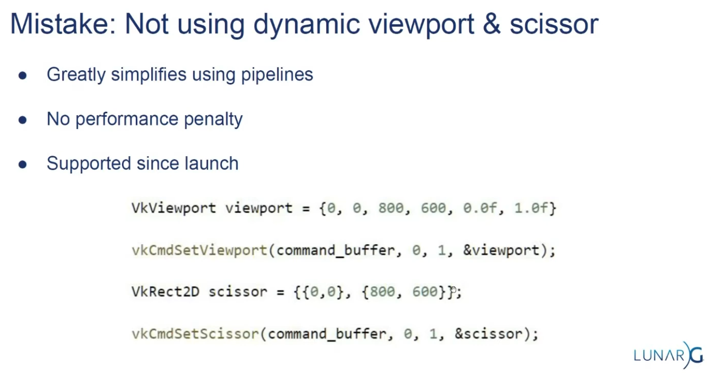 .
.
-
-
-
Multi-Sampling
Setup
-
VkPipelineMultisampleStateCreateInfo.-
rasterizationSamples-
If the bound pipeline was created without a
VkAttachmentSampleCountInfoAMDorVkAttachmentSampleCountInfoNVstructure, and themultisampledRenderToSingleSampledfeature is not enabled, and the current render pass instance was begun withvkCmdBeginRenderingwith aVkRenderingInfo:colorAttachmentCountparameter greater than 0, then each element of theVkRenderingInfo:pColorAttachmentsarray with aimageViewnot equal toNULL_HANDLEmust have been created with a sample count equal to the value ofrasterizationSamplesfor the bound graphics pipeline. -
Is a VkSampleCountFlagBits value specifying the number of samples used in rasterization. This value is ignored for the purposes of setting the number of samples used in rasterization if the pipeline is created with the
DYNAMIC_STATE_RASTERIZATION_SAMPLES_EXTdynamic state set, but ifDYNAMIC_STATE_SAMPLE_MASK_EXTdynamic state is not set, it is still used to define the size of thepSampleMaskarray as described below.
-
-
sampleShadingEnable-
It can be used to enable Sample Shading .
-
-
minSampleShading-
Specifies a minimum fraction of sample shading if
sampleShadingEnableisTRUE.
-
-
pSampleMask-
Is a pointer to an array of
VkSampleMaskvalues used in the sample mask test .
-
-
alphaToCoverageEnable-
Controls whether a temporary coverage value is generated based on the alpha component of the fragment’s first color output as specified in the Multisample Coverage section.
-
-
alphaToOneEnable-
Controls whether the alpha component of the fragment’s first color output is replaced with one as described in Multisample Coverage .
-
-
flags-
Reserved for future use.
-
-
Resolving
-
-
resolveMode-
Is a VkResolveModeFlagBits value defining how data written to
imageViewwill be resolved intoresolveImageView. -
If
resolveModeis notRESOLVE_MODE_NONE, andresolveImageViewis not NULL_HANDLE , a render pass multisample resolve operation is defined for the attachment subresource. -
RESOLVE_MODE_NONE-
Specifies that no resolve operation is done.
-
-
RESOLVE_MODE_SAMPLE_ZERO-
Specifies that result of the resolve operation is equal to the value of sample 0.
-
-
RESOLVE_MODE_AVERAGE-
Specifies that result of the resolve operation is the average of the sample values.
-
-
RESOLVE_MODE_MIN-
Specifies that result of the resolve operation is the minimum of the sample values.
-
-
RESOLVE_MODE_MAX-
Specifies that result of the resolve operation is the maximum of the sample values.
-
-
RESOLVE_MODE_EXTERNAL_FORMAT_DOWNSAMPLE_ANDROID-
Specifies that rather than a multisample resolve, a single sampled color attachment will be downsampled into a Y′CBCR format image specified by an external Android format. Unlike other resolve modes, implementations can resolve multiple times during rendering, or even bypass writing to the color attachment altogether, as long as the final value is resolved to the resolve attachment. Values in the G, B, and R channels of the color attachment will be written to the Y, CB, and CR channels of the external format image, respectively. Chroma values are calculated as if sampling with a linear filter from the color attachment at full rate, at the location the chroma values sit according to VkPhysicalDeviceExternalFormatResolvePropertiesANDROID ::
externalFormatResolveChromaOffsetX, VkPhysicalDeviceExternalFormatResolvePropertiesANDROID ::externalFormatResolveChromaOffsetY, and the chroma sample rate of the resolved image. -
No range compression or Y′CBCR model conversion is performed by
RESOLVE_MODE_EXTERNAL_FORMAT_DOWNSAMPLE_ANDROID; applications have to do these conversions themselves. Value outputs are expected to match those that would be read through a Y′CBCR sampler usingSAMPLER_YCBCR_MODEL_CONVERSION_RGB_IDENTITY. The color space that the values should be in is defined by the platform and is not exposed via Vulkan.
-
-
-
resolveImageView-
Is an image view used to write resolved data at the end of rendering.
-
-
resolveImageLayout-
Is the layout that
resolveImageViewwill be in during rendering. -
If
imageViewis notNULL_HANDLEandresolveModeis notRESOLVE_MODE_NONE,resolveImageLayoutmust not beIMAGE_LAYOUT_UNDEFINED,IMAGE_LAYOUT_DEPTH_STENCIL_READ_ONLY_OPTIMAL,IMAGE_LAYOUT_SHADER_READ_ONLY_OPTIMAL,IMAGE_LAYOUT_TRANSFER_SRC_OPTIMAL,IMAGE_LAYOUT_ZERO_INITIALIZED_EXT,IMAGE_LAYOUT_TRANSFER_DST_OPTIMAL, orIMAGE_LAYOUT_PREINITIALIZED
-
-
-
From Multisample, to Singlesample.
-
Combine sample values from a single pixel in a multisample attachment and store the result to the corresponding pixel in a single sample attachment.
-
Multisample resolve operations for attachments execute in the
PIPELINE_STAGE_COLOR_ATTACHMENT_OUTPUTpipeline stage. A final resolve operation for all pixels in the render area happens-after any recorded command which writes a pixel via the multisample attachment to be resolved or an explicit alias of it in the subpass that it is specified. -
Any single sample attachment specified for use in a multisample resolve operation may have its contents modified at any point once rendering begins for the render pass instance.
-
Reads from the multisample attachment can be synchronized with
ACCESS_COLOR_ATTACHMENT_READ. Access to the single sample attachment can be synchronized withACCESS_COLOR_ATTACHMENT_READandCOLOR_ATTACHMENT_WRITE. These pipeline stage and access types are used whether the attachments are color or depth/stencil attachments. -
When using render pass objects, a subpass dependency specified with the above pipeline stages and access flags will ensure synchronization with multisample resolve operations for any attachments that were last accessed by that subpass. This allows later subpasses to read resolved values as input attachments.
-
Resolve operations only update values within the defined render area for the render pass instance. However, any writes performed by a resolve operation (as defined by its access masks) to a given attachment may read and write back any memory locations within the image subresource bound for that attachment. For depth/stencil images, if
separateDepthStencilAttachmentAccessisFALSE, writes to one aspect may also result in read-modify-write operations for the other aspect. If the subresource is bound to an attachment with feedback loop enabled , implementations must not access pixels outside of the render area. -
As entire subresources could be accessed by multisample resolve operations, applications cannot safely access values outside of the render area via aliased resources during a render pass instance when a multisample resolve operation is performed.
-
If
RESOLVE_MODE_AVERAGEis used, and the source format is a floating-point or normalized type, the sample values for each pixel are resolved with implementation-defined numerical precision. -
If the numeric format of the resolve attachment uses sRGB encoding, the implementation should convert samples from nonlinear to linear before averaging samples as described in the “sRGB EOTF” section of the Khronos Data Format Specification . In this case, the implementation must convert the linear averaged value to nonlinear before writing the resolved result to resolve attachment.
-
The resolve mode and store operation are independent; it is valid to write both resolved and unresolved values, and equally valid to discard the unresolved values while writing the resolved ones.
Multisampling Anti-Aliasing (MSAA)
-
Using only one sample per pixel which is equivalent to no multisampling.
-
Maximum supported :
-
Can be extracted from
VkPhysicalDevicePropertiesassociated with our selected physical device. -
The highest sample count that Color Image and Depth Image (Buffer) will be the maximum we can support.
-
-
What to Multisample :
-
The render target.
-
If using a depth image, it should also be multisampled.
-
-
Limitations :
-
The multisampled image should only have one mip level.
-
This is enforced by the Vulkan specification in case of images with more than one sample per pixel.
-
-
Multi-sampled images cannot be presented directly.
-
This requirement does not apply to the depth buffer, since it won’t be presented at any point.
-
-
-
DOs :
-
Use 4x MSAA if possible; it’s not expensive and provides good image quality improvements.
-
Use
loadOp = LOAD_OP_CLEARorloadOp = LOAD_OP_DONT_CAREfor multisampled images. -
Use
storeOp = STORE_OP_DONT_CAREfor multisampled images. -
Use
LAZILY_ALLOCATEDmemory to back the allocated multisampled images; they do not need to be persisted into main memory and therefore do not need physical backing storage. -
Use
pResolveAttachmentsin a subpass to automatically resolve a multisampled color buffer into a single-sampled color buffer. -
Use
KHR_depth_stencil_resolvein a subpass to automatically resolve a multisampled depth buffer into a single-sampled depth buffer. Typically this is only useful if the depth buffer is going to be used further, in most cases it is transient and does not need to be resolved.
-
-
Avoid :
-
Avoid using
vkCmdResolveImage(); this has a significant negative impact on bandwidth and performance. -
Avoid using
loadOp = LOAD_OP_LOADfor multisampled image attachments. -
Avoid using
storeOp = STORE_OP_STOREfor multisampled image attachments. -
Avoid using more than 4x MSAA without checking performance.
-
-
Impact :
-
Failing to get an inline resolve can result in substantially higher memory bandwidth and reduced performance.
-
Manually writing and resolving a 4x MSAA 1080p surface at 60 FPS requires 3.9GB/s of memory bandwidth compared to just 500MB/s when using an inline resolve.
-
-
-
Sample Shading :
-
There are certain limitations of our current MSAA implementation which may impact the quality of the output image in more detailed scenes. For example, we're currently not solving potential problems caused by shader aliasing, i.e. MSAA only smoothens out the edges of geometry but not the interior filling. This may lead to a situation when you get a smooth polygon rendered on screen but the applied texture will still look aliased if it contains high contrasting colors. One way to approach this problem is to enable Sample Shading which will improve the image quality even further, though at an additional performance cost:
void createLogicalDevice() { ... deviceFeatures.sampleRateShading = TRUE; // enable sample shading feature for the device ... } void createGraphicsPipeline() { ... multisampling.sampleShadingEnable = TRUE; // enable sample shading in the pipeline multisampling.minSampleShading = .2f; // min fraction for sample shading; closer to one is smoother ... }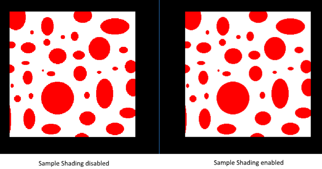 .
.
-
-
Performance Tests :
-
(2025-09-07)
-
Done anyway, very approximate.
-
-
MSAAx8 = 900 fps
-
MSAAx4 = 1250fps
-
MSAAx2 = 1550fps
-
MSAA off = 2100fps
-
As samples increase, frame time increases approximately by factors 1.35 (x2), 1.68 (x4) and 2.33 (x8) compared to the case without MSAA — this is consistent with substantial per-sample cost increase, but is not strictly linear with the number of samples (e.g.: x4 is not exactly 4× nor x8 exactly 8×).
-
Fragment Shader
-
Programmable stage.
-
Is invoked for every fragment that survives and determines which framebuffer(s) the fragments are written to and with which color and depth values. It can do this using the interpolated data from the vertex shader, which can include things like texture coordinates and normals for lighting.
-
The
VkShaderModuleobjects are created from shader byte code.
Color Blending
-
Fixed-function stage.
-
Controls how the GPU combines the fragment shader’s output with what is already in the framebuffer.
-
Applies operations to mix different fragments that map to the same pixel in the framebuffer. Fragments can simply overwrite each other, add up or be mixed based upon transparency.
-
After a fragment shader has returned a color, it needs to be combined with the color that is already in the framebuffer.
-
This transformation is known as color blending, and there are two ways to do it:
-
Mix the old and new value to produce a final color
-
Combine the old and new value using a bitwise operation
-
-
Example :
-
If enabled blending in the pipeline, it will blend the frag shader result with the render_target previous visual.
-
So if the frag result has alpha < 1.0, it will blend the clear color with the frag shader result, giving it a "transparent visual" against the clear color.
-
-
vkPipelineColorBlendAttachmentState.-
Contains the configuration per attached framebuffer.
-
This per-framebuffer struct allows you to configure the first way of color blending:
// Pseudo-code if (blendEnable) { finalColor.rgb = (srcColorBlendFactor * newColor.rgb) <colorBlendOp> (dstColorBlendFactor * oldColor.rgb); finalColor.a = (srcAlphaBlendFactor * newColor.a) <alphaBlendOp> (dstAlphaBlendFactor * oldColor.a); } else { finalColor = newColor; } finalColor = finalColor & colorWriteMask; -
The most common way to use color blending is to implement alpha blending, where we want the new color to be blended with the old color based on its opacity.
-
The
finalColorshould then be computed as follows:finalColor.rgb = newAlpha * newColor + (1 - newAlpha) * oldColor; finalColor.a = newAlpha.a; -
This can be achieved with the following parameters:
colorBlendAttachment.blendEnable = vk::True;
colorBlendAttachment.srcColorBlendFactor = vk::BlendFactor::eSrcAlpha;
colorBlendAttachment.dstColorBlendFactor = vk::BlendFactor::eOneMinusSrcAlpha;
colorBlendAttachment.colorBlendOp = vk::BlendOp::eAdd;
colorBlendAttachment.srcAlphaBlendFactor = vk::BlendFactor::eOne;
colorBlendAttachment.dstAlphaBlendFactor = vk::BlendFactor::eZero;
colorBlendAttachment.alphaBlendOp = vk::BlendOp::eAdd;
-
-
blendEnable-
If set to
FALSE, then the new color from the fragment shader is passed through unmodified. Otherwise, the two mixing operations are performed to compute a new color. -
The resulting color is AND’d with the
colorWriteMaskto determine which channels are actually passed through.
-
-
-
VkPipelineColorBlendStateCreateInfo.-
Contains the global color blending settings.
-
References the array of structures for all the framebuffers and allows you to set blend constants that you can use as blend factors in the aforementioned calculations.
-
attachmentCount-
Is the number of
VkPipelineColorBlendAttachmentStateelements inpAttachments. -
It is ignored if the pipeline is created with
DYNAMIC_STATE_COLOR_BLEND_ENABLET,DYNAMIC_STATE_COLOR_BLEND_EQUATION_EXT, andDYNAMIC_STATE_COLOR_WRITE_MASK_EXTdynamic states set, and eitherDYNAMIC_STATE_COLOR_BLEND_ADVANCED_EXTset or the advancedBlendCoherentOperations feature is not enabled.
-
-
pAttachments-
Is a pointer to an array of
VkPipelineColorBlendAttachmentStatestructures defining blend state for each color attachment. -
It is ignored if the pipeline is created with
DYNAMIC_STATE_COLOR_BLEND_ENABLET,DYNAMIC_STATE_COLOR_BLEND_EQUATION_EXT, andDYNAMIC_STATE_COLOR_WRITE_MASK_EXTdynamic states set, and eitherDYNAMIC_STATE_COLOR_BLEND_ADVANCED_EXTset or the advancedBlendCoherentOperations feature is not enabled.
-
-
logicOpEnable-
Controls whether to apply Logical Operations .
-
-
logicOp-
Selects which logical operation to apply.
-
If you want to use the second method of blending (a bitwise combination), then you should set
logicOpEnabletoTRUE.-
Note that this will automatically disable the first method, as if you had set
blendEnabletoFALSEfor every attached framebuffer.
-
-
colorWriteMaskwill also be used in this mode to determine which channels in the framebuffer will actually be affected. -
If disabled both modes, the fragment colors will be written to the framebuffer unmodified.
-
-
blendConstants-
Is a pointer to an array of four values used as the R, G, B, and A components of the blend constant that are used in blending, depending on the blend factor .
-
-
flags
-
Creation
Setup
-
vkGraphicsPipelineCreateInfo.-
flags-
DISABLE_OPTIMIZATION-
Specifies that the created pipeline will not be optimized.
-
Using this flag may reduce the time taken to create the pipeline.
-
-
-
renderPass-
Is set to
nullptrbecause we’re using dynamic rendering instead of a traditional render pass.
-
-
basePipelineHandle -
basePipelineIndex -
Graphics Pipelines Inheritance :
-
Vulkan allows you to create a new graphics pipeline by deriving from an existing pipeline.
-
The idea of pipeline derivatives is that it is less expensive to set up pipelines when they have much functionality in common with an existing pipeline and switching between pipelines from the same parent can also be done quicker.
-
You can either specify the handle of an existing pipeline with
basePipelineHandleor reference another pipeline that is about to be created by index withbasePipelineIndex. -
These values are only used if the
VPIPELINE_CREATE_DERIVATIVEflag is also specified in theflagsfield ofVkGraphicsPipelineCreateInfo.
-
-
-
-
device-
Is the logical device that creates the graphics pipelines.
-
-
pipelineCache-
Is either
NULL_HANDLE, indicating that pipeline caching is disabled, or to enable caching, the handle of a valid VkPipelineCache object. The implementation must not access this object outside of the duration of this command. -
A pipeline cache can be used to store and reuse data relevant to pipeline creation across multiple calls to
vkCreateGraphicsPipelinesand even across program executions if the cache is stored to a file. This makes it possible to significantly speed up pipeline creation at a later time.
-
-
createInfoCount-
Is the length of the
pCreateInfosandpPipelinesarrays.
-
-
pCreateInfos-
Is a pointer to an array of VkGraphicsPipelineCreateInfo structures.
-
-
pAllocator-
Controls host memory allocation as described in the Memory Allocation chapter.
-
-
pPipelines-
Is a pointer to an array of VkPipeline handles in which the resulting graphics pipeline objects are returned.
-
-
Dynamic Rendering Extra Steps
-
Changes to the
vkGraphicsPipelineCreateInfo:-
The
vkGraphicsPipelineCreateInfomust be created without aVkRenderPass. -
The
VkPipelineRenderingCreateInfomust be included in thepNext.-
If a graphics pipeline is created with a valid
VkRenderPass, the parameters of theVkPipelineRenderingCreateInfoare ignored.
-
-
-
VkPipelineRenderingCreateInfo.-
colorAttachmentCount-
Is the number of entries in
pColorAttachmentFormats
-
-
pColorAttachmentFormats-
Is a pointer to an array of
VkFormatvalues defining the format of color attachments used in this pipeline.
-
-
depthAttachmentFormat-
Is a
VkFormatvalue defining the format of the depth attachment used in this pipeline.
-
-
stencilAttachmentFormat-
Is a
VkFormatvalue defining the format of the stencil attachment used in this pipeline.
-
-
viewMask-
Is a bitfield of view indices describing which views are active during rendering.
-
It must match VkRenderingInfo.viewMask when rendering.
-
As defined in
VkRenderingInfo:-
Is a bitfield of view indices describing which views are active during rendering, when it is not
0. -
If
viewMaskis not0, multiview is enabled.
-
-
-
-
Formats :
-
If
depthAttachmentFormat,stencilAttachmentFormat, or any element ofpColorAttachmentFormatsisUNDEFINED, it indicates that the corresponding attachment is unused within the render pass. -
Valid formats indicate that an attachment can be used - but it is still valid to set the attachment to
NULLwhen beginning rendering.
-
-
Managing Pipelines and Reducing overhead
-
Tips and Tricks: Vulkan Dos and Don’ts .
-
Use pipeline cache.
-
Use specialization constants.
-
This may cause a possible decrease in the number of instructions and registers used by the shader.
-
Specialization constants can also be used instead of offline shader permutations to minimize the amount of bytecode that needs to be shipped with an application.
-
-
Switching pipelines:
-
Avoid frequently switching between pipelines that use different sets of pipeline stages.
-
Minimize the number of
vkCmdBindPipelinecalls, each call has significant CPU cost and GPU cost.-
Consider sorting of drawcalls and/or using a low number of dynamic states.
-
-
Switching on/off the tessellation, geometry, task and mesh shaders is an expensive operation.
-
-
Draw calls:
-
Group draw calls, taking into account what kinds of shaders they use.
-
-
The Problem
-
Immutable Pipelines.
-
Each combination of inputs require a dedicated pipeline.
-
Shader, topology, blend mode, vertex layout, cull mode, etc.
-
So if we want to do things like toggle depth-testing on and off, we will need 2 pipelines.
-
-
Causes a combinatorial explosion of variants.
-
10.000's of pipelines for shipping titles.
-
-
Building pipelines is a very expensive operation, and we want to minimize the number of pipelines used as its critical for performance.
My decisions
-
(2025-08-10)
-
Dynamic State is a must.
-
The use of Shader Object still seems new and may introduce some extra complexity in certain cases.
-
I don't know about mobile support.
-
-
The use of Graphics Pipeline Libraries sounds interesting, but at the same time it seems limiting in some moments, for Geometry and Tessellation Shaders.
-
I don't know about mobile support.
-
-
Overall, I believe that refactoring a game object to use Shader Object or Graphics Pipeline Libraries sounds "simple", since it's more about how the pipeline is constructed than how one interacts with shaders or descriptor sets. In other words, it seems like an okay decision to make in the future.
-
Considering the low support, and the fact that I don't have so many pipelines in mind that actually make these solutions necessary, I prefer to use graphics pipelines manually, in the "default" way.
-
Regardless, I believe that using Shader Object or Graphics Pipeline does not remove the need to worry about pipeline caching or precautions to avoid switching the pipeline binding all the time.
-
Correct. Extensions change how pipelines are created/linked but do not remove the performance considerations around pipeline creation, pipeline cache usage, or minimizing pipeline re-binding at draw time. Vendors and platform docs recommend pipeline caches, pre-creation, and minimizing pipeline binds.
-
-
What I will do, therefore: caching and sorting of pipelines based on similarity. I will worry more about binding the pipeline in command buffers and their descriptor sets, than the process of facilitating the creation of new pipelines.
-
This plan aligns with widely recommended practical strategies: use pipeline caches (persist to disk where possible), sort and batch by pipeline/descriptor similarity, and create pipelines asynchronously (background threads) to avoid stutter. These practices address the main runtime pain points regardless of whether you later adopt shader-object or pipeline-library extensions.
-
Your current decisions are internally consistent and align with common, pragmatic industry practice: prefer stable/default graphics pipelines with pipeline caching, sorting, and background creation as the primary strategy, while keeping code organized so you can adopt
EXT_shader_objectorEXT_graphics_pipeline_librarylater if/when device support and measured benefits justify the switch.
-
Mutability with
VkDynamicState
-
Implemented.
-
It's a must .
-
Not everything has to be immutable.
-
Set desired state while recording command buffers.
-
Over 70 states can be dynamic.
-
If we don't use this, we would need to create new pipelines if we wanted to change the resolution of our rendering.
No pipelines, with
EXT_shader_object
-
Sample .
-
Article .
-
Support :
-
Coverage .
-
(2025-09-08) 11.29%.
-
33.8% Windows.
-
26.3% Linux.
-
0% Android.
-
-
-
Shader Object and implementation in Odin {7:30 -> 11:56} .
-
Questions :
-
I don't know where
pColorAttachmentFormatsanddepthAttachmentFormatare specified.-
I don't know if it's even necessary to specify them anywhere.
-
The words
attachmentorformatdo not appear anywhere in the sample or in the spec of the extension.
-
pipeline_rendering_create_info := vk.PipelineRenderingCreateInfo{ sType = .PIPELINE_RENDERING_CREATE_INFO, colorAttachmentCount = 1, pColorAttachmentFormats = format, depthAttachmentFormat = .D24_UNORM_S8_UINT, stencilAttachmentFormat = {}, viewMask = 0, } -
-
Code .
create_shaders :: proc() { push_constant_ranges := []vk.PushConstantRange { // Pipeline { stageFlags = {.VERTEX, .FRAGMENT}, size = 128, } } /* This is not used in the Shader Object. The only place that needs this in its code, is when making the call `vk.CmdPushConstants(cmd, g.pipeline_layout, {.VERTEX, .FRAGMENT}, 0, size_of(push), &push)`. */ pipeline_layout_ci := vk.PipelineLayoutCreateInfo { sType = .PIPELINE_LAYOUT_CREATE_INFO, // flags = {}, // setLayoutCount = 1, // pSetLayouts = {}, pushConstantRangeCount = u32(len(push_constant_ranges)), pPushConstantRanges = raw_data(push_constant_ranges), } check(vk.CreatePipelineLayout(g.device, &pipeline_layout_ci, nil, &g.pipeline_layout)) // Pipeline vert_code := load_file("shaders/shader.vert.spv", context.temp_allocator) // Shader_Info frag_code := load_file("shaders/shader.frag.spv", context.temp_allocator) // Shader_Info shader_cis := [2]vk.ShaderCreateInfoEXT { { sType = .SHADER_CREATE_INFO_EXT, codeType = .SPIRV, codeSize = len(vert_code), pCode = raw_data(vert_code), pName = "main", stage = {.VERTEX}, nextStage = {.FRAGMENT}, flags = {.LINK_STAGE}, // setLayoutCount: u32, // pSetLayouts: [^]DescriptorSetLayout, pushConstantRangeCount = u32(len(push_constant_ranges)), pPushConstantRanges = raw_data(push_constant_ranges), // pSpecializationInfo: ^SpecializationInfo, }, { sType = .SHADER_CREATE_INFO_EXT, codeType = .SPIRV, codeSize = len(frag_code), pCode = raw_data(frag_code), pName = "main", stage = {.FRAGMENT}, // nextStage: ShaderStageFlags, flags = {.LINK_STAGE}, // setLayoutCount: u32, // pSetLayouts: [^]DescriptorSetLayout, pushConstantRangeCount = u32(len(push_constant_ranges)), pPushConstantRanges = raw_data(push_constant_ranges), // pSpecializationInfo: ^SpecializationInfo, }, } check(vk.CreateShadersEXT(g.device, 2, raw_data(&shader_cis), nil, raw_data(&g.shaders))) } destroy_shaders :: proc() { vk.DestroyPipelineLayout(g.device, g.pipeline_layout, nil) for shader in g.shaders do vk.DestroyShaderEXT(g.device, shader, nil) } render :: proc(cmd: vk.CommandBuffer) { shader_stages := [2]vk.ShaderStageFlags { {.VERTEX}, {.FRAGMENT} } vk.CmdBindShadersEXT(cmd, 2, raw_data(&shader_stages), raw_data(&g.shaders)) vk.CmdSetVertexInputEXT(cmd, 0, nil, 0, nil) // Shader_Info: vk.VertexInputBindingDescription, vk.VertexInputAttributeDescription. vk.CmdSetViewportWithCount(cmd, 1, &vk.Viewport { // Dynamic width = f32(g.swapchain.width), height = f32(g.swapchain.height), minDepth = 0, maxDepth = 1, }) vk.CmdSetScissorWithCount(cmd, 1, &vk.Rect2D { extent = {width = g.swapchain.width, height = g.swapchain.height} // Dynamic }) vk.CmdSetRasterizerDiscardEnable(cmd, false) // Pipeline vk.CmdSetPrimitiveTopology(cmd, .TRIANGLE_LIST) // Pipeline vk.CmdSetPrimitiveRestartEnable(cmd, false) // Pipeline vk.CmdSetRasterizationSamplesEXT(cmd, {._1}) // Pipeline sample_mask := vk.SampleMask(1) vk.CmdSetSampleMaskEXT(cmd, {._1}, &sample_mask) // Pipeline vk.CmdSetAlphaToCoverageEnableEXT(cmd, false) // Pipeline vk.CmdSetPolygonModeEXT(cmd, .FILL) // Pipeline vk.CmdSetCullMode(cmd, {}) // Pipeline vk.CmdSetFrontFace(cmd, .COUNTER_CLOCKWISE) // Pipeline vk.CmdSetDepthTestEnable(cmd, false) // Pipeline vk.CmdSetDepthWriteEnable(cmd, false) // Pipeline vk.CmdSetDepthBiasEnable(cmd, false) // Pipeline vk.CmdSetStencilTestEnable(cmd, false) // Pipeline b32_false := b32(false) vk.CmdSetColorBlendEnableEXT(cmd, 0, 1, &b32_false) // Pipeline color_mask := vk.ColorComponentFlags { .R, .G, .B, .A } vk.CmdSetColorWriteMaskEXT(cmd, 0, 1, &color_mask) // Pipeline Push :: struct { color: [3]f32, } push := Push { color = { 0, 0.5, 0 } } vk.CmdPushConstants(cmd, g.pipeline_layout, {.VERTEX, .FRAGMENT}, 0, size_of(push), &push) // vk.CmdBindDescriptorSets // Dynamic vk.CmdDraw(cmd, 3, 1, 0, 0) } -
-
Ditch pipelines entirely.
-
Bind compiled shader stages.
-
It was created primarily for the Nintendo Switch, to reduce the performance gap between Vulkan and NVN (the Switch's native API), which doesn't even have the concept of pipeline state objects and map almost 1:1 to how Nvidia hardware works.
-
If you want to use Shader Objects, the reason should be "I find it much easier to use/maintain". Because once you grow you'll encounter friction as the extension is meant for porting old engines, and goes against new features.
-
Support :
-
Hard to recommend, as for limited support.
-
Currently only available on AMD & Nvidia.
-
It provides an emulation layer, which make them usable on any device not natively supporting them. but you need to provide the dll file for the layer along with the application.
-
-
Shaders :
-
This extension introduces a new object type
VkShaderEXTwhich represents a single compiled shader stage.VkShaderEXTobjects may be created either independently or linked with otherVkShaderEXTobjects created at the same time. To createVkShaderEXTobjects, applications callvkCreateShadersEXT(). -
This function compiles the source code for one or more shader stages into
VkShaderEXTobjects. -
Optional Linking :
-
Whenever
createInfoCountis greater than one, the shaders being created may optionally be linked together. Linking allows the implementation to perform cross-stage optimizations based on a promise by the application that the linked shaders will always be used together. -
Though a set of linked shaders may perform anywhere between the same to substantially better than equivalent unlinked shaders, this tradeoff is left to the application and linking is never mandatory.
-
To specify that shaders should be linked, include the
SHADER_CREATE_LINK_STAGE_EXTflag in each of theVkShaderCreateInfoEXTstructures passed tovkCreateShadersEXT(). The presence or absence ofSHADER_CREATE_LINK_STAGE_EXTmust match across allVkShaderCreateInfoEXTstructures passed to a singlevkCreateShadersEXT()call: i.e., if any member ofpCreateInfosincludesSHADER_CREATE_LINK_STAGE_EXTthen all other members must include it too.SHADER_CREATE_LINK_STAGE_EXTis ignored ifcreateInfoCountis one, and a shader created this way is considered unlinked.
-
-
The stage of the shader being compiled is specified by
stage. Applications must also specify which stage types will be allowed to immediately follow the shader being created. For example, a vertex shader might specify anextStagevalue ofSHADER_STAGE_FRAGMENTto indicate that the vertex shader being created will always be followed by a fragment shader (and never a geometry or tessellation shader). Applications that do not know this information at shader creation time or need the same shader to be compatible with multiple subsequent stages can specify a mask that includes as many valid next stages as they wish. For example, a vertex shader can specify anextStagemask ofSHADER_STAGE_GEOMETRY | SHADER_STAGE_FRAGMENTto indicate that the next stage could be either a geometry shader or fragment shader (but not a tessellation shader). -
etc, see the spec .
-
Reducing compilation overhead, with
EXT_graphics_pipeline_libraries
-
Sample .
-
Support :
-
Release: (2022-06-03).
-
Coverage .
-
(2025-09-08) 18.7% coverage.
-
40.7% Windows.
-
40.6% Linux.
-
4.88% Android.
-
-
-
-
I've read until the Dynamic State header.
-
-
Allows separate compilation of different parts of the graphics pipeline. With this it’s now possible to split up the monolithic pipeline creation into different steps and re-use common parts shared across different pipelines.
-
Compared to monolithic pipeline state, this results in faster pipeline creation times, making this extension a good fit for applications and games that do a lot of pipeline creation at runtime.
-
Libraries are partial pipeline objects which cannot be bound directly; they are linked together to form a final executable pipeline.
-
Encourages reuse of compilation work and reduces startup/runtime stutter for games with many similar pipelines.
-
Because libraries are precompiled partial pipelines, linking is generally cheaper than compiling whole pipelines from scratch.
-
Individual pipelines stages :
-
The monolithic pipeline state has been split into distinct parts that can be compiled independently.
-
Vertex Input Interface :
-
Contains the information that would normally be provided to the full pipeline state object by VkPipelineVertexInputStateCreateInfo and VkPipelineInputAssemblyStateCreateInfo.
-
"For our engine, this information is not known until draw time, so a pipeline for this stage is still hashed and created at draw time."
-
This stage has no shader code and thus the driver can create it quickly and there are also a fairly small number of these objects.
-
-
Pre-Rasterization Shaders :
-
Contains vertex, tessellation, and geometry shader stages along with the state associated with VkPipelineViewportStateCreateInfo , VkPipelineRasterizationStateCreateInfo , VkPipelineTessellationStateCreateInfo , and VkRenderPass (or dynamic rendering).
-
The only information you actually need to create the pre-rasterization shader is the SPIR-V code and pipeline layout.
-
-
Fragment Shader :
-
Contains the fragment shader along with the state in VkPipelineDepthStencilStateCreateInfo and VkRenderPass (or dynamic rendering - although in that case only the viewMask is required).
-
If combined with dynamic rendering you can create the fragment shader pipeline with only the SPIR-V and the pipeline layout.
This allows the driver to do the heavy lifting of lowering to hardware instructions for the pre-rasterization and fragment shaders with very little information.
-
-
Fragment Output Interface :
-
Contains the VkPipelineColorBlendStateCreateInfo, VkPipelineMultisampleStateCreateInfo, and VkRenderPass (or dynamic rendering)
-
Like with the Vertex Input Interface, this stage requires information that we don’t know until draw time, so this state is also hashed and the Fragment Output Interface pipeline is created at draw time.
-
It is expected to be very quick to create and also relatively small in number.
-
-
-
Final link :
-
With all four individual pipeline library stages created, an application can perform a final link to a full pipeline. This final link is expected to be extremely fast - the driver will have done the shader compilation for the individual stages and thus the link can be performed at draw time at a reasonable cost.
-
This is where the big benefit of the extension comes in: we’ve pre-created all of our pre-rasterization and fragment shaders, hashed the small number of vertex input/fragment output interfaces, and can on-demand create a fast linked pipeline library at draw time, thus avoiding a dreaded hitch.
-
-
If shader compilation stutter is your concern, this extension is the way to go. This extension lets you create partially-constructed PSOs (Pipeline State Objects) (e.g. one for Vertex another for Pixel Shader), and then combine them to generate the final PSO. This allows splitting the huge monolithic block into smaller monolithic blocks that are easier to handle and design around, making the API more D3D11-like (D3D11 has monolithic Rasterizer State blocks and Blend State blocks).
-
Creating pipeline libraries :
-
Creating a pipeline library (part) is similar to creating a pipeline, with the difference that you only need to specify the properties required for that specific pipeline state.
-
E.g. for the vertex input interface you only specify input assembly and vertex input state, which is all required to define the interfaces to a vertex shader.
-
VkGraphicsPipelineLibraryCreateInfoEXT library_info{}; library_info.sType = STRUCTURE_TYPE_GRAPHICS_PIPELINE_LIBRARY_CREATE_INFO_EXT; library_info.flags = GRAPHICS_PIPELINE_LIBRARY_VERTEX_INPUT_INTERFACE_EXT; VkPipelineInputAssemblyStateCreateInfo input_assembly_state = vkb::initializers::pipeline_input_assembly_state_create_info(PRIMITIVE_TOPOLOGY_TRIANGLE_LIST, 0, FALSE); VkPipelineVertexInputStateCreateInfo vertex_input_state = vkb::initializers::pipeline_vertex_input_state_create_info(); std::vector<VkVertexInputBindingDescription> vertex_input_bindings = { vkb::initializers::vertex_input_binding_description(0, sizeof(Vertex), VERTEX_INPUT_RATE_VERTEX), }; std::vector<VkVertexInputAttributeDescription> vertex_input_attributes = { vkb::initializers::vertex_input_attribute_description(0, 0, FORMAT_R32G32B32_SFLOAT, 0), vkb::initializers::vertex_input_attribute_description(0, 1, FORMAT_R32G32B32_SFLOAT, sizeof(float) * 3), vkb::initializers::vertex_input_attribute_description(0, 2, FORMAT_R32G32_SFLOAT, sizeof(float) * 6), }; vertex_input_state.vertexBindingDescriptionCount = static_cast<uint32_t>(vertex_input_bindings.size()); vertex_input_state.pVertexBindingDescriptions = vertex_input_bindings.data(); vertex_input_state.vertexAttributeDescriptionCount = static_cast<uint32_t>(vertex_input_attributes.size()); vertex_input_state.pVertexAttributeDescriptions = vertex_input_attributes.data(); VkGraphicsPipelineCreateInfo pipeline_library_create_info{}; pipeline_library_create_info.sType = STRUCTURE_TYPE_GRAPHICS_PIPELINE_CREATE_INFO; pipeline_library_create_info.flags = PIPELINE_CREATE_LIBRARY_KHR | PIPELINE_CREATE_RETAIN_LINK_TIME_OPTIMIZATION_INFO_EXT; pipeline_library_create_info.sType = STRUCTURE_TYPE_GRAPHICS_PIPELINE_CREATE_INFO; pipeline_library_create_info.pNext = &library_info; pipeline_library_create_info.pInputAssemblyState = &input_assembly_state; pipeline_library_create_info.pVertexInputState = &vertex_input_state; vkCreateGraphicsPipelines(get_device().get_handle(), pipeline_cache, 1, &pipeline_library_create_info, nullptr, &pipeline_library.vertex_input_interface); -
-
Deprecating shader modules :
-
With this extension, creating shader modules with
vkCreateShaderModulehas been deprecated and you can instead just pass the shader module create info viapNextinto your pipeline shader stage create info. This change bypasses a useless copy and is recommended. -
You can see this in the pre-rasterization and fragment shader library setup parts of the sample below.
VkShaderModuleCreateInfo shader_module_create_info{}; shader_module_create_info.sType = STRUCTURE_TYPE_SHADER_MODULE_CREATE_INFO; shader_module_create_info.codeSize = static_cast<uint32_t>(spirv.size()) * sizeof(uint32_t); shader_module_create_info.pCode = spirv.data(); VkPipelineShaderStageCreateInfo shader_Stage_create_info{}; shader_Stage_create_info.sType = STRUCTURE_TYPE_PIPELINE_SHADER_STAGE_CREATE_INFO; // Chain the shader module create info shader_Stage_create_info.pNext = &shader_module_create_info; shader_Stage_create_info.stage = SHADER_STAGE_VERTEX; shader_Stage_create_info.pName = "main"; VkGraphicsPipelineCreateInfo pipeline_library_create_info{}; pipeline_library_create_info.stageCount = 1; pipeline_library_create_info.pStages = &shader_Stage_create_info; -
-
Linking executables :
-
Once all pipeline (library) parts have been created, the pipeline executable can be linked together from them:
std::vector<VkPipeline> libraries = { pipeline_library.vertex_input_interface, pipeline_library.pre_rasterization_shaders, fragment_shader, pipeline_library.fragment_output_interface }; // Link the library parts into a graphics pipeline VkPipelineLibraryCreateInfoKHR linking_info{}; linking_info.sType = STRUCTURE_TYPE_PIPELINE_LIBRARY_CREATE_INFO_KHR; linking_info.libraryCount = static_cast<uint32_t>(libraries.size()); linking_info.pLibraries = libraries.data(); VkGraphicsPipelineCreateInfo executable_pipeline_create_info{}; executable_pipeline_create_info.sType = STRUCTURE_TYPE_GRAPHICS_PIPELINE_CREATE_INFO; executable_pipeline_create_info.pNext = &linking_info; executable_pipeline_create_info.flags = PIPELINE_CREATE_LINK_TIME_OPTIMIZATION_EXT; VkPipeline executable = NULL_HANDLE; vkCreateGraphicsPipelines(get_device().get_handle(), thread_pipeline_cache, 1, &executable_pipeline_create_info, nullptr, &executable);-
This will result in the pipeline state object to be used at draw time.
-
A note on
PIPELINE_CREATE_LINK_TIME_OPTIMIZATION_EXT: This is an optimization flag. If specified, implementations are allowed to do additional optimization passes. This may increase build times but can in turn result in lower runtime costs.
-
-
Independent Descriptor Sets :
-
Imagine a situation where the vertex and fragment stage accesses two different descriptor sets.
// Vertex Shader layout(set = 0) UBO_X; // Fragment Shader layout(set = 1) UBO_Y;-
Normally when compiling a pipeline, both stages are together and internally a driver will reserve 2 separate descriptor slots for
UBO_XandUBO_Y. When using graphics pipeline libraries, the driver will see the fragment shader only uses a single descriptor set. It might internally map it toset 0, but when linking the two libraries, there will be a collision. ThePIPELINE_LAYOUT_CREATE_INDEPENDENT_SETS_EXTflag ensures the driver will be able to handle this case and not have any collisions. There are some extra constraints when using this flag, but the Validation Layers will detect them for you.
-
-
-
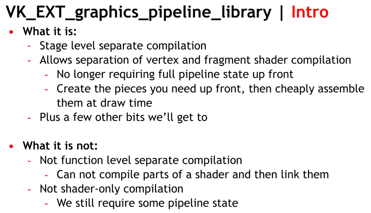 .
.
-
 .
.
-
Same number of pipelines, but acquired through reuse, instead of recompilation.
-
Think of the link step as additive, instead of multiplicative.
-
-
 .
.
-
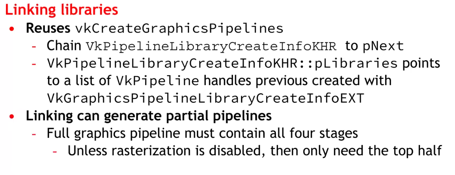 .
.
-
Considerations :
-
At the time it was said there would be an impact on CPU.
-
It was unknown whether it was compatible with mobile or not.
-
No libraries were made for Geometry and Tessellation Shaders, as they are difficult.
-
-
~One pipeline per shader variant
-
It is the cause of the problem listed above.
-
Causes a combinatorial explosion of variants.
Single pipeline, branch inside shader (material ID / push constant)
-
No way, seems horrible.
Optimizations
Pipeline Cache, with
VkPipelineCache
-
It allows the driver to reuse previously computed pipeline artifacts across pipeline creations (and you can persist cache data between runs).
-
Avoids repeating expensive driver work; shortens startup time by reusing previously compiled artifacts.
-
Creating a Vulkan pipeline requires compiling
VkShaderModuleinternally. This will have a significant increase in frame time if performed at runtime. To reduce this time, you can provide a previously initialisedVkPipelineCacheobject when calling thevkCreateGraphicsPipelinesorvkCreateComputePipelinesfunctions. This object behaves like a cache container which stores the pipeline internal representation for reuse. In order to benefit from using aVkPipelineCacheobject, the data recorded during pipeline creation needs to be saved to disk and reused between application runs. -
Vulkan allows an application to obtain the binary data of a
VkPipelineCacheobject and save it to a file on disk before terminating the application. This operation can be achieved using two calls to thevkGetPipelineCacheDatafunction to obtain the size andVkPipelineCacheobject’s binary data. In the next application run, theVkPipelineCachecan be initialised with the previous run’s data. This will allow thevkCreateGraphicsPipelinesorvkCreateComputePipelinesfunctions to reuse the baked state and avoid repeating costly operations such as shader compilation. -
How to use it :
-
Create one
VkPipelineCachefor related pipeline creation operations (often one per device). -
Pass it into
vkCreateGraphicsPipelinesfor every create call. -
On exit (or periodically) call
vkGetPipelineCacheDataand write to disk; on startup feed that blob intovkCreatePipelineCacheto prepopulate the cache.
-
-
KHR_pipeline_binary-
VkPipelineCacheobjects were designed to enable a Vulkan driver to reuse blobs of state or shader code between different pipelines. Originally, the idea was that the driver would know best which parts of state could be reused, and applications only needed to manage storage and threading, simplifying developer code. -
Over time however,
VkPipelineCacheobjects proved to be too opaque, prompting the Vulkan Working Group to release a number of extensions to provide more application control over them. The current capabilities ofVkPipelineCacheobjects satisfies many applications, but has shortcomings in more advanced use cases. -
Previous difficulties :
-
The
VkPipelineCacheAPI provides no control over the lifetime of the binary objects that it contains. An application wanting to implement an LRU cache, for example, has a hard time usingVkPipelineCacheobjects. -
Some applications maintain a cache of VkPipeline objects. The VkPipelineCache API makes it impossible to efficiently associate the cached binary objects within a VkPipelineCache object with the application’s own cache entries.
-
-
What’s more, most drivers maintain an internal cache of pipeline-derived binary objects. In some cases, it would be beneficial for the application to directly interact with that internal cache, especially on some specialized platforms.
-
The new
KHR_pipeline_binaryextension introduces a clean new approach that provides applications with access to binary blobs and the information necessary for optimal caching, while smoothly integrating with the application’s own caching mechanisms. -
It’s worth noting that the
EXT_shader_objectextension already includes analogous functionality toKHR_pipeline_binary. The two extensions were worked on concurrently to provide a universally available solution, including devices where theEXT_shader_objectextension cannot yet be supported. -
Applications that do not need the advanced functionality of the new KHR_pipeline_binary extension can continue to use VkPipelineCache objects for their simplicity and optimized implementation. But developers that are not satisfied with the VkPipelineCache API should read on to learn more about this powerful new approach.
-
Article .
-
Read up to 'Caching With KHR_pipeline_binary'.
-
-
Optimizing the Shader with
KHR_buffer_device_address
-
See Vulkan#Physical Storage Buffer (KHR_buffer_device_address) .
-
Support :
Pipeline derivatives
-
A creation mechanism to tell the driver that one pipeline is a parent and others are children (derivatives).
-
The driver may avoid redoing expensive compile/link steps and reuse intermediate data from the parent, reducing creation time.
-
The intent is faster creation of children by reusing work/data from the parent.
-
The pipeline creation API provides no way to tell it what state will change. The idea being that, since the implementation can see the parent's state, and it can see what you ask of the child's state, it can tell what's different.
-
Is it worth it? NO.
-
TLDR :
-
No vendor is actually recommending the use of pipeline derivatives, except maybe to speed up pipeline creation.
-
-
Tips and Tricks: Vulkan Dos and Don’ts .
-
Don’t expect speedup from Pipeline Derivatives.
-
-
Vulkan Usage Recommendations , Samsung
-
Pipeline derivatives let applications express "child" pipelines as incremental state changes from a similar "parent"; on some architectures, this can reduce the cost of switching between similar states.
-
Many mobile GPUs gain performance primarily through pipeline caches, so pipeline derivatives often provide no benefit to portable mobile applications.
-
Recommendations:
-
Create pipelines early in application execution. Avoid pipeline creation at draw time.
-
Use a single pipeline cache for all pipeline creation.
-
Write the pipeline cache to a file between application runs.
-
Avoid pipeline derivatives.
-
-
-
Vulkan Best Practice for Mobile Developers - Pipeline Management , Arm Software, Jul 11, 2019
-
Don't create pipelines at draw time without a pipeline cache (introduces performance stutters).
-
Don't use pipeline derivatives as they are not supported.
-
-
Vulkan Samples, LunarG - API-Samples/pipeline_derivative/pipeline_derivative.cpp
-
This sample creates pipeline derivative and draws with it. Pipeline derivatives should allow for faster creation of pipelines.
-
In this sample, we'll create the default pipeline, but then modify it slightly and create a derivative.
-
The derivative will be used to render a simple cube. We may later find that the pipeline is too simple to show any speedup, or that replacing the fragment shader is too expensive, so this sample can be updated then.
-
-
-
Typical use case :
-
Many pipelines that differ only by a few fields (e.g., different specializations or small state changes).
-
-
How to use :
-
Create a base pipeline with
PIPELINE_CREATE_ALLOW_DERIVATIVES. -
For similar pipelines (small shader or state differences), create child pipelines with
PIPELINE_CREATE_DERIVATIVEand setbasePipelineHandleorbasePipelineIndexpointing to the base.
-
-
How it affects the pipeline workflow :
-
Can materially reduce pipeline creation cost when many similar pipelines are needed.
-
Useful at runtime if you must create many variants quickly.
-
Still creates separate pipeline objects (state memory + driver bookkeeping).
-
-
Not guaranteed to be implemented with identical performance gains on all drivers; behavior is driver-dependent.
Compute Pipeline
-
-
Cool.
-
A compute shader is used to determine an array of positions, then render each point in a graphics pipeline using POINTS as the primitive.
-
-
Poor explanation, with possibly useful code, in Vulkan .
-
The video's code may be useful based on what I saw.
-
Though, the video itself is meh.
-
-
A compute shader maps pretty well of how a GPU operates; which is not really the case of a Graphics Pipeline.
Use cases
-
Calculate images from complex postprocessing chains.
-
Raytracing or other non-geometry drawing.
Creation
-
We need to create first the pipeline layout for it, and then hook a single shader module for its code.
-
Once its built, we can execute the compute shader by first calling
VkCmdBindPipelineand then callingVkCmdDispatch.
Using
-
You generally want to use a memory barrier after the dispatch of the compute shader, so you wait for the compute shader to finish to finally access its data; if that's what you want to do.
-
In OpenGL the
GL_SHADER_STORAGE_BARRIERis used.
-
Workgroup
-
vkCmdDispatch. -
For an image, I had the decision to only use 2 of those dimensions, that way we can execute one workgroup per group of pixels in the image.
-
When executing compute shaders, they will get executed in groups of N lanes/threads.
-
The most difficult part is the decision of partitioning the compute shader between Workgroups and Local Size.
-
Local Size is also called Workgroup Size, representing the number of threads inside each Workgroup.
-
 .
.
-
The code is in OpenGL, but the concept is the same.
-
-
The size of the local_size should be ideally related to the size of a warp/wavefront from the GPU, so you don't waste processing power.
-
For
layout(local_size_x = 3, local_size_y = 4, local_size_z = 2), you'll use3 * 4 * 2 = 24threads, which is not ideal for a NVIDIA warp size. -
 .
.
GLSL Built-in Variables

Examples
-
The shader code is a very simple shader that will create a gradient from the coordinates of the global invocation ID.
//GLSL version to use
#version 460

//size of a workgroup for compute
layout (local_size_x = 16, local_size_y = 16) in;

//descriptor bindings for the pipeline
layout(rgba16f,set = 0, binding = 0) uniform image2D image;


void main()
{
    ivec2 texelCoord = ivec2(gl_GlobalInvocationID.xy);
    ivec2 size = imageSize(image);

    if(texelCoord.x < size.x && texelCoord.y < size.y)
    {
        vec4 color = vec4(0.0, 0.0, 0.0, 1.0);

        if(gl_LocalInvocationID.x != 0 && gl_LocalInvocationID.y != 0)
        {
            color.x = float(texelCoord.x)/(size.x);
            color.y = float(texelCoord.y)/(size.y);
        }

        imageStore(image, texelCoord, color);
    }
}
-
Inside the shader itself, we can see
layout (local_size_x = 16, local_size_y = 16) in;(z=1 by default).-
By doing that, we are setting the size of a single workgroup.
-
This means that for every work unit from the
vkCmdDispatch, we will have 16x16 lanes of execution, which works well to write into a 16x16 pixel square.
-
-
The next layout statement is for the shader input through descriptor sets. We are setting a single image2D as set 0 and binding 0 within that set.
-
If local invocation ID is 0 on either X or Y, we will just default to black. This is going to create a grid that will directly display our shader workgroup invocations.
-
On the shader code, we can access what the lane index is through
gl_LocalInvocationIDvariable. -
There is also
gl_GlobalInvocationIDandgl_WorkGroupID. By using those variables we can find out what pixel exactly do we write from each lane.
Compute Shader Raytracing
Resources
-
Resources are views of memory with associated formatting and dimensionality.
-
Nvidia: Make sure to always use the minimum set of resource usage flags. Redundant flags may trigger redundant flushes and stalls in barriers and slow down your app unnecessarily.
Primary resources
-
Buffers.
-
Provide access to raw arrays of bytes
-
-
Images.
-
Can be multidimensional and may have associated metadata.
-
-
Tensors.
-
Can be multidimensional, contain format information like images and may have associated metadata.
-
-
Samplers.
-
Used to sample from images at certain coordinates, producing interpolated color values.
-
-
-
Uses buffers as the backing store for opaque data structures.
-
-
-
Uses buffers as the backing store for opaque data structures.
-
Used for realtime raytracing.
-
Buffers
-
Buffers in Vulkan are regions of memory used for storing arbitrary data that can be read by the graphics card.
-
They are essentially unformatted arrays of bytes.
-
Types of Buffers :
-
Unformatted array .
-
Uniform Buffer :
-
It remains uniform during the execution of a command (like a draw call).
-
Only load operations (read only).
-
"Read" == "Load".
-
This allows the GPU to cache them efficiently.
-
-
Loaded into L2, and further, into a L1 cache.
-
-
Storage Buffers :
-
Allow Load and Store operations.
-
Supports atomic operations.
-
Data can be loaded from GPU memory into L2->L1 caches, but can also store data from shaders into memory.
-
-
Texel Buffers :
-
Uniform Texel Buffer.
-
Storage Texel Buffer.
-
Formatted view.
-
-
Dynamic Buffers :
-
Dynamic Uniform Buffer.
-
Dynamic Texel Buffer.
-
-
etc.
-
-
Queues :
-
Just like the images in the Swapchain, buffers can also be owned by a specific queue family or be shared between multiple at the same time.
-
The buffer will only be used from the graphics queue, so we can stick to exclusive access.
-
-
Create
-
-
VkBuffer-
A chunk of GPU visible memory
-
-
VkBufferCreateInfo-
size-
Specifies the size of the buffer in bytes. Calculating the byte size of the vertex data is straightforward with
sizeof.
-
-
usage-
Indicates for which purposes the data in the buffer is going to be used.
-
It is possible to specify multiple purposes using a bitwise or.
-
-
flags-
Is used to configure sparse buffer memory, which is not relevant right now. We'll leave it at the default value of
0.
-
-
sharingMode-
Specifying the sharing mode of the buffer when it will be accessed by multiple queue families.
-
The buffer will only be used from the graphics queue, so we can stick to exclusive access.
-
NVIDIA:
-
VkSharingModeis ignored by the driver, soSHARING_MODE_CONCURRENTincurs no overhead relative toSHARING_MODE_EXCLUSIVE.
-
-
SHARING_MODE_EXCLUSIVE-
Specifies that access to any range or image subresource of the object will be exclusive to a single queue family at a time.
-
-
SHARING_MODE_CONCURRENT-
Specifies that concurrent access to any range or image subresource of the object from multiple queue families is supported.
-
-
-
-
Copy
-
Minimum Alignment :
-
-
optimalBufferCopyOffsetAlignment-
Is the optimal buffer offset alignment in bytes for vkCmdCopyBufferToImage2 , vkCmdCopyBufferToImage , vkCmdCopyImageToBuffer2 , and vkCmdCopyImageToBuffer .
-
This value is also the optimal host memory offset alignment in bytes for vkCopyMemoryToImage and vkCopyImageToMemory .
-
The per texel alignment requirements are enforced, but applications should use the optimal alignment for optimal performance and power use.
-
The value must be a power of two.
-
-
optimalBufferCopyRowPitchAlignment-
Is the optimal buffer row pitch alignment in bytes for vkCmdCopyBufferToImage2 , vkCmdCopyBufferToImage , vkCmdCopyImageToBuffer2 , and vkCmdCopyImageToBuffer .
-
This value is also the optimal host memory row pitch alignment in bytes for vkCopyMemoryToImage and vkCopyImageToMemory .
-
Row pitch is the number of bytes between texels with the same X coordinate in adjacent rows (Y coordinates differ by one). The per texel alignment requirements are enforced, but applications should use the optimal alignment for optimal performance and power use.
-
The value must be a power of two.
-
-
-
Images
-
Images contain format information. Can be multidimensional and may have associated metadata.
-
An Image, unlike a Buffer, is almost always used within a View.
-
A texture you can write to and read from.
-
VkImage. -
Stored as :
-
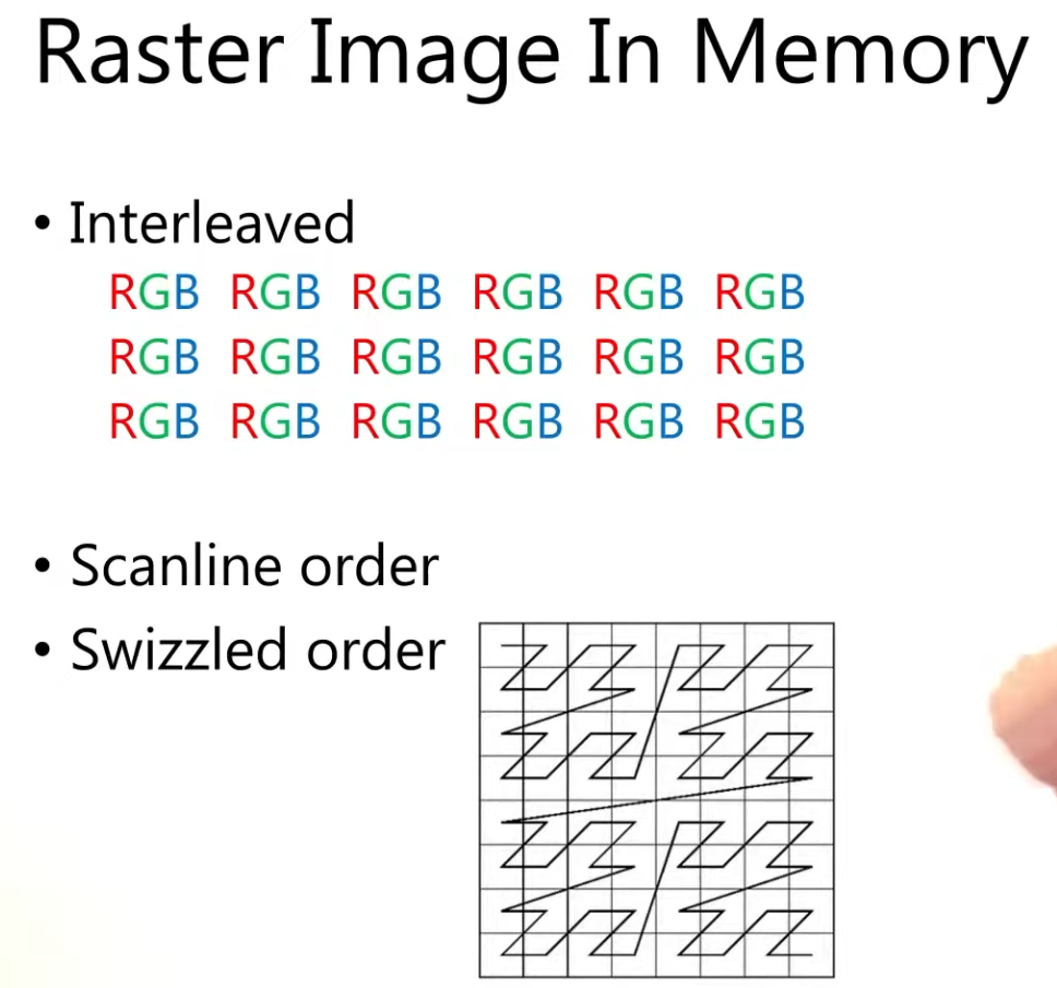 .
.
-
Create
-
-
ImageType -
extent-
Specifies the dimensions of the image, basically how many texels there are on each axis.
-
That’s why
extent.depthmust be1instead of0.
-
-
format -
tiling -
initialLayout-
Can only be one of these 3:
-
UNDEFINED-
Not usable by the GPU and the very first transition will discard the texels.
-
-
PREINITIALIZED-
Not usable by the GPU, but the first transition will preserve the texels.
-
-
ZERO_INITIALIZED_EXT-
Only if zeroInitializeDeviceMemory feature is enabled.
-
-
-
There are a few situations where it is necessary for the texels to be preserved during the first transition.
-
One example would be if you wanted to use an image as a staging image in combination with the
TILING_LINEARlayout. In that case, you’d want to upload the texel data to it and then transition the image to be a transfer source without losing the data.
-
-
However, we usually don't need this property and can use
UNDEFINED, as we can transition the image to be a transfer destination and then copy texel data to it from a buffer object.
-
-
usage -
samples-
For multisampling.
-
Only relevant for images that will be used as attachments.
-
The default for non-multisampled images is one sample.
-
-
mipLevels-
For mipmapping.
-
-
flags-
Related to sparse images.
-
Sparse images are images where only certain regions are actually backed by memory.
-
If you were using a 3D texture for a voxel terrain, for example, then you could use this to avoid allocating memory to store large volumes of "air" values.
-
-
sharingMode-
Specifies the sharing mode of the image when it will be accessed by multiple queue families.
-
-
queueFamilyIndexCount-
Is the number of entries in the
pQueueFamilyIndicesarray.
-
-
pQueueFamilyIndices-
Is a pointer to an array of queue families that will access this image. It is ignored if
sharingModeis notSHARING_MODE_CONCURRENT.
-
-
Types
-
Tells Vulkan with what kind of coordinate system the texels in the image are going to be addressed.
-
1D images
-
Can be used to store an array of data or a gradient.
-
-
2D images
-
Are mainly used for textures.
-
-
3D images
-
Can be used to store voxel volumes, for example.
-
Usages
-
Storage Image :
-
Load and Store.
-
Similar to a Storage Buffer.
-
-
Sampled Image :
-
Only load operations (read only).
-
Similar to Uniform Buffers.
-
The coordinates are between 0.0 and 1.0.
-
If a coordinate doesn't match exactly a pixel, then the result is an interpolation between the neighbouring pixels.
-
-
Input Attachment :
-
Only load operations (read only).
-
Within a renderpass.
-
Framebuffer-local.
-
Access to single coordinate only.
-
No access to other coordinates in that image.
-
-
Formats
-
Formats .
-
R8G8B8_SRGB-
Channels stored as 0–255.
-
After conversion, the values are in the 0-1 floating-point range.
-
Interpreted using the sRGB nonlinear transfer function (gamma correction).
-
When sampled, values are converted to linear color space in the shader automatically.
-
-
R8G8B8_UNORM-
Each 8-bit channel is an unsigned normalized integer.
-
Storage range: 0–255.
-
Interpreted as floating-point in the shader:
-
0 → 0.0
-
255 → 1.0
-
Linear mapping between.
-
-
-
R8G8B8_SNORM-
Each 8-bit channel is a signed normalized integer.
-
Storage range: –128 to +127.
-
Interpreted as floating-point in the shader:
-
–128 → –1.0
-
+127 → +1.0
-
Linear mapping between.
-
-
Tiling
-
Nvidia: Always use
TILING_OPTIMAL.-
TILING_LINEARis not optimal. Use a staging buffer andvkCmdCopyBufferToImage()to update images on the device.
-
-
Unlike the layout of an image, the tiling mode cannot be changed at a later time.
-
TILING_OPTIMAL-
The layout is opaque/driver-chosen.
-
Is described as an implementation-dependent (opaque) arrangement that the driver/GPU may reorder/tile texels for efficient access; it is the intended layout for GPU use.
-
When to use :
-
Image is used as a framebuffer attachment, sampled texture, or otherwise heavily used by the GPU (most rendering targets).
-
You want the GPU/driver to choose a layout that maximizes memory locality and bandwidth for rendering.
-
You will perform GPU-side post-processing / tonemapping / sampling / blits before presentation.
-
-
-
TILING_LINEAR-
The layout is row-major/predictable.
-
Lays out texels in row-major order (with row padding possible) and is the layout for which
vkGetImageSubresourceLayoutreturns meaningful offsets for host access; that is the mechanism used when an application needs direct CPU mapping/reading of image memory.-
However, in practice applications usually do GPU render → copy to a host-visible staging buffer/image rather than render directly into a linear-host-visible image.
-
-
LINEAR tiling does have functional and performance limitations (fewer supported formats/usages and worse GPU access patterns), which is why it’s rarely used for main rendering; typical use cases are CPU upload/download, debugging, or very small offscreen images. It is not only theoretically usable for CPU readback, but that is the primary practical use. You must query format/usage support for linear tiling because many formats or usages are unsupported in LINEAR.
-
When to use :
-
You explicitly need to map the image memory from the CPU (direct host read/write) and the driver reports support for the requested format/usage in linear tiling.
-
Use cases: readback for screenshots/debugging, direct CPU uploads for small resources, or special interop scenarios where a row-major layout is required.
-
-
-
GPU OPTIMAL to Host-Visible :
-
Strategy applied for 'creating a texture from file' .
-
If you want to be able to directly access texels in the memory of the image, then you must use
TILING_LINEAR. We will be using a staging buffer instead of a staging image, so this won't be necessary. We will be usingTILING_OPTIMALfor efficient access from the shader.
-
-
TLDR :
OPTIMAL+ explicit transfer to a host-visible staging resource when needed. -
Create your render target as
OPTIMALand allocateDEVICE_LOCALmemory (fast GPU local). After rendering, copy or blit the image to a host-visible staging resource (either a buffer viavkCmdCopyImageToBufferor a LINEAR image) and map that staging resource for CPU access. This avoids depending on limited linear support and keeps the GPU path fast.
-
Layouts
-
GENERAL-
Supports all types of device access, unless specified otherwise.
-
If the
unifiedImageLayoutsfeature is enabled, theGENERALimage layout may be used in place of the other layouts where allowed with no loss of performance.-
VkPhysicalDeviceUnifiedImageLayoutsFeaturesKHR.-
Can be included in the
pNextchain of theVkPhysicalDeviceFeatures2structure passed tovkGetPhysicalDeviceFeatures2. -
KHR_unified_image_layouts.-
This extension significantly simplifies synchronization in Vulkan by removing the need for image layout transitions in most cases. In particular, it guarantees that using the
GENERALlayout everywhere possible is just as efficient as using the other layouts. -
In the interest of simplifying synchronization in Vulkan, this extension removes image layouts altogether as much as possible. As such, this extension is fairly simple.
-
Proposal .
-
Article .
-
Interacts with :
-
VERSION_1_3
-
EXT_attachment_feedback_loop_layout
-
KHR_dynamic_rendering
-
-
Support :
-
-
unifiedImageLayouts(boolean)-
Specifies whether usage of
GENERAL, where valid, incurs no loss in efficiency. -
Additionally, it indicates whether it can be used in place of
ATTACHMENT_FEEDBACK_LOOP_OPTIMAL_EXT.
-
-
unifiedImageLayoutsVideo(boolean)-
Specifies whether
GENERALcan be used in place of any of the following image layouts with no loss in efficiency. -
VIDEO_DECODE_DST -
VIDEO_DECODE_SRC -
VIDEO_DECODE_DPB -
VIDEO_ENCODE_DST -
VIDEO_ENCODE_SRC -
VIDEO_ENCODE_DPB -
VIDEO_ENCODE_QUANTIZATION_MAP
-
-
-
-
It can be a useful catch-all image layout, but there are situations where a dedicated image layout must be used instead. For example:
-
PRESENT_SRC. -
SHARED_PRESENT. -
VIDEO_DECODE_SRC,VIDEO_DECODE_DST, andVIDEO_DECODE_DPBwithout theunifiedImageLayoutsVideofeature. -
VIDEO_ENCODE_SRC,VIDEO_ENCODE_DST, andVIDEO_ENCODE_DPBwithout theunifiedImageLayoutsVideofeature. -
VIDEO_ENCODE_QUANTIZATION_MAPwithout theunifiedImageLayoutsVideofeature.
-
-
While
GENERALsuggests that all types of device access are possible, it does not mean that all patterns of memory accesses are safe in all situations.-
Common Render Pass Data Races outlines some situations where data races are unavoidable. For example, when a subresource is used as both an attachment and a sampled image (i.e., not an input attachment), enabling feedback loop adds extra guarantees which
GENERALalone does not.
-
-
-
Only in
initialLayout:-
UNDEFINED-
Specifies that the layout is unknown.
-
This layout can be used as the
initialLayoutmember of VkImageCreateInfo . Image memory cannot be transitioned into this layout. -
This layout can be used in place of the current image layout in a layout transition, but doing so will cause the contents of the image’s memory to be undefined.
-
-
PREINITIALIZED-
Specifies that an image’s memory is in a defined layout and can be populated by data, but that it has not yet been initialized by the driver.
-
This layout can be used as the
initialLayoutmember of VkImageCreateInfo . Image memory cannot be transitioned into this layout. -
This layout is intended to be used as the initial layout for an image whose contents are written by the host, and hence the data can be written to memory immediately, without first executing a layout transition.
-
Currently,
PREINITIALIZEDis only useful with linear images because there is not a standard layout defined forTILING_OPTIMALimages.
-
-
ZERO_INITIALIZED_EXT-
Specifies that an image’s memory is in a defined layout and is zeroed, but that it has not yet been initialized by the driver.
-
This layout can be used as the
initialLayoutmember of VkImageCreateInfo . Image memory cannot be transitioned into this layout. -
This layout is intended to be used as the initial layout for an image whose contents are already zeroed, either from being explicitly set to zero by an application or from being allocated with
MEMORY_ALLOCATE_ZERO_INITIALIZE_EXT. -
Only if zeroInitializeDeviceMemory feature is enabled.
-
-
-
Transfer :
-
TRANSFER_SRC_OPTIMAL-
It must only be used as a source image of a transfer command (see the definition of
PIPELINE_STAGE_TRANSFER). -
This layout is valid only for image subresources of images created with the
USAGE_TRANSFER_SRCusage bit enabled.
-
-
TRANSFER_DST_OPTIMAL-
It must only be used as a destination image of a transfer command.
-
This layout is valid only for image subresources of images created with the
USAGE_TRANSFER_DSTusage bit enabled.
-
-
-
Present :
-
PRESENT_SRC-
It must only be used for presenting a presentable image for display.
-
-
SHARED_PRESENT-
Is valid only for shared presentable images, and must be used for any usage the image supports.
-
-
-
Read :
-
READ_ONLY_OPTIMAL-
Specifies a layout allowing read only access as an attachment, or in shaders as a sampled image, combined image/sampler, or input attachment.
-
-
DEPTH_READ_ONLY_OPTIMAL-
Specifies a layout for the depth aspect of a depth/stencil format image allowing read-only access as a depth attachment or in shaders as a sampled image, combined image/sampler, or input attachment.
-
-
STENCIL_READ_ONLY_OPTIMAL-
Specifies a layout for the stencil aspect of a depth/stencil format image allowing read-only access as a stencil attachment or in shaders as a sampled image, combined image/sampler, or input attachment.
-
-
DEPTH_STENCIL_READ_ONLY_OPTIMAL-
Specifies a layout for both the depth and stencil aspects of a depth/stencil format image allowing read only access as a depth/stencil attachment or in shaders as a sampled image, combined image/sampler, or input attachment.
-
It is equivalent to
DEPTH_READ_ONLY_OPTIMALandSTENCIL_READ_ONLY_OPTIMAL.
-
-
SHADER_READ_ONLY_OPTIMAL-
Specifies a layout allowing read-only access in a shader as a sampled image, combined image/sampler, or input attachment.
-
This layout is valid only for image subresources of images created with the
USAGE_SAMPLEDorUSAGE_INPUT_ATTACHMENTusage bits enabled.
-
-
-
Attachments :
-
ATTACHMENT_OPTIMAL-
Specifies a layout that must only be used with attachment accesses in the graphics pipeline.
-
-
COLOR_ATTACHMENT_OPTIMAL-
It must only be used as a color or resolve attachment in a
VkFramebuffer. -
This layout is valid only for image subresources of images created with the
COLOR_ATTACHMENTusage bit enabled. -
Nvidia: Use
COLOR_ATTACHMENT_OPTIMALimage layout for color attachments.
-
-
DEPTH_ATTACHMENT_OPTIMAL-
Specifies a layout for the depth aspect of a depth/stencil format image allowing read and write access as a depth attachment.
-
-
STENCIL_ATTACHMENT_OPTIMAL-
Specifies a layout for the stencil aspect of a depth/stencil format image allowing read and write access as a stencil attachment.
-
-
DEPTH_STENCIL_ATTACHMENT_OPTIMAL-
Specifies a layout for both the depth and stencil aspects of a depth/stencil format image allowing read and write access as a depth/stencil attachment.
-
Equivalent to
DEPTH_ATTACHMENT_OPTIMALandSTENCIL_ATTACHMENT_OPTIMAL.
-
-
ATTACHMENT_FEEDBACK_LOOP_OPTIMAL_EXT-
It must only be used as either a color attachment or depth/stencil attachment and/or read-only access in a shader as a sampled image, combined image/sampler, or input attachment.
-
This layout is valid only for image subresources of images created with the
USAGE_ATTACHMENT_FEEDBACK_LOOPusage bit enabled and either theUSAGE_COLOR_ATTACHMENTorUSAGE_DEPTH_STENCIL_ATTACHMENTand either theUSAGE_INPUT_ATTACHMENTorUSAGE_SAMPLEDusage bits enabled.
-
-
LAYOUT_RENDERING_LOCAL_READ-
It must only be used as either a storage image, or a color or depth/stencil attachment and an input attachment.
-
This layout is valid only for image subresources of images created with either
USAGE_STORAGE, or bothUSAGE_INPUT_ATTACHMENTand either ofUSAGE_COLOR_ATTACHMENTorUSAGE_DEPTH_STENCIL_ATTACHMENT.
-
-
Attachment Fragment Shading Rate
-
FRAGMENT_SHADING_RATE_ATTACHMENT_OPTIMAL-
It must only be used as a fragment shading rate attachment or shading rate image .
-
This layout is valid only for image subresources of images created with the
USAGE_FRAGMENT_SHADING_RATE_ATTACHMENTusage bit enabled.
-
-
-
Fragment Density Map :
-
FRAGMENT_DENSITY_MAP_OPTIMAL_EXT-
It must only be used as a fragment density map attachment in a
VkRenderPass. -
This layout is valid only for image subresources of images created with the
USAGE_FRAGMENT_DENSITY_MAPusage bit enabled.
-
-
-
-
Read / Attachment :
-
DEPTH_READ_ONLY_STENCIL_ATTACHMENT_OPTIMAL-
Specifies a layout for depth/stencil format images allowing read and write access to the stencil aspect as a stencil attachment, and read only access to the depth aspect as a depth attachment or in shaders as a sampled image, combined image/sampler, or input attachment.
-
Equivalent to
DEPTH_READ_ONLY_OPTIMALandSTENCIL_ATTACHMENT_OPTIMAL.
-
-
DEPTH_ATTACHMENT_STENCIL_READ_ONLY_OPTIMAL-
Specifies a layout for depth/stencil format images allowing read and write access to the depth aspect as a depth attachment, and read only access to the stencil aspect as a stencil attachment or in shaders as a sampled image, combined image/sampler, or input attachment.
-
Equivalent to
DEPTH_ATTACHMENT_OPTIMALandSTENCIL_READ_ONLY_OPTIMAL.
-
-
-
Video :
-
VIDEO_DECODE_DST-
It must only be used as a decode output picture in a video decode operation .
-
This layout is valid only for image subresources of images created with the
VIDEO_DECODE_DSTusage bit enabled.
-
-
VIDEO_DECODE_SRC-
Reserved for future use.
-
-
VIDEO_DECODE_DPB-
It must only be used as an output reconstructed picture or an input reference picture in a video decode operation .
-
This layout is valid only for image subresources of images created with the
USAGE_VIDEO_DECODE_DPBusage bit enabled.
-
-
VIDEO_ENCODE_DST-
Reserved for future use.
-
-
VIDEO_ENCODE_SRC-
It must only be used as an encode input picture in a video encode operation .
-
This layout is valid only for image subresources of images created with the
USAGE_VIDEO_ENCODE_SRCusage bit enabled.
-
-
VIDEO_ENCODE_DPB-
It must only be used as an output reconstructed picture or an input reference picture in a video encode operation .
-
This layout is valid only for image subresources of images created with the
USAGE_VIDEO_ENCODE_DPBusage bit enabled.
-
-
VIDEO_ENCODE_QUANTIZATION_MAP-
It must only be used as a quantization map in a video encode operation .
-
This layout is valid only for image subresources of images created with the
VIDEO_ENCODE_QUANTIZATION_DELTA_MAPorVIDEO_ENCODE_EMPHASIS_MAPusage bit enabled.
-
-
-
TENSOR_ALIASING_ARM-
Specifies the layout that an image created with
TILING_OPTIMALmust be in for it and a tensor bound to the same aliased range of memory to consistently interpret the data in memory. -
See https://registry.khronos.org/vulkan/specs/latest/html/vkspec.html#resources-memory-aliasing for a complete set of rules for tensor/image aliasing.
-
This layout is valid only for image subresources of images created with
USAGE_TENSOR_ALIASING.
-
Image Views
-
An image view references a specific part of an image to be used.
-
VkImageViewCreateInfo-
viewType-
Allows you to treat images as 1D textures, 2D textures, 3D textures and cube maps.
-
-
format -
components-
Allows you to swizzle the color channels around. For example, you can map all of the channels to the red channel for a monochrome texture. You can also map constant values of
0and1to a channel. In our case we'll stick to the default mapping.
-
-
subresourceRange-
Describes what the image's purpose is and which part of the image should be accessed. Our images will be used as color targets without any mipmapping levels or multiple layers.
-
If you were working on a stereographic 3D application, then you would create a Swapchain with multiple layers. You could then create multiple image views for each image representing the views for the left and right eyes by accessing different layers.
-
-
Copy: Blit (Copy image to image)
-
Transfer a rectangular region of pixel data from one image to another.
-
Unlike a raw copy (
vkCmdCopyImage), a blit can perform scaling and apply filtering (FILTER_LINEARorFILTER_NEAREST), which is consistent with the historical meaning of bit block transfer with optional transformations. -
Name :
-
Comes from bit block transfer (sometimes shortened to blt_).
-
It was introduced in the 1970s in the context of 2D graphics systems, particularly at Xerox PARC.
-
The idea was to copy rectangular blocks of bits (pixels) from one place in memory to another, often with operations like scaling, masking, or raster operations.
-
-
-
commandBuffer -
pBlitImageInfo-
srcImage-
Is the source image.
-
-
srcImageLayout-
Is the layout of the source image subresources for the blit.
-
-
dstImage-
Is the destination image.
-
-
dstImageLayout-
Is the layout of the destination image subresources for the blit.
-
-
regionCount-
Is the number of regions to blit.
-
-
pRegions-
Defines source and destination subresources, offsets, and extents.
-
Can define multiple regions in a single blit call.
-
For each element of the
pRegionsarray, a blit operation is performed for the specified source and destination regions. -
Offset :
-
The offset entries specify two corners of the rectangular/box region to blit (one corner and the opposite corner).
-
You normally set
offsets[0]to the region origin (frequently{0,0,0}) andoffsets[1]to the region end ({width, height, depth}), i.e. the bounds. -
If left unspecified, that produces the common
{0,0,0} -> {w,h,1}box. -
The Vulkan spec requires both offsets be provided and documents constraints on them (e.g. for 2D images
zmust be 0/1).
-
-
srcSubresource-
Is the subresource to blit from.
-
-
srcOffsets-
Is a pointer to an array of two VkOffset3D structures specifying the bounds of the source region within
srcSubresource.
-
-
dstSubresource-
Is the subresource to blit into.
-
-
dstOffsets-
Is a pointer to an array of two VkOffset3D structures specifying the bounds of the destination region within
dstSubresource.
-
-
filter-
Is a VkFilter specifying the filter to apply if the blits require scaling.
-
Determines how pixels are sampled if scaling occurs.
-
FILTER_NEARESTfor nearest-neighbor scaling. -
FILTER_LINEARfor linear interpolation.
-
-
Their layouts must be valid for transfer operations (
TRANSFER_SRC_OPTIMALandTRANSFER_DST_OPTIMAL).
-
-
Restrictions
-
Blit operations are supported only if the format and the physical device support
FORMAT_FEATURE_BLIT_SRCandFORMAT_FEATURE_BLIT_DST. -
Some formats (like depth/stencil) do not support blitting.
-
Multisampled images cannot be used directly as source or destination.
-
Compression
Depth
Depth Tests
Shader
-
gl_FragDepth-
Available only in the fragment shader.
-
Is an output variable that is used to establish the depth value for the current fragment.
-
It is a
float. -
If depth buffering is enabled and no shader writes to
gl_FragDepth, then the fixed function value for depth will be used (this value is contained in the z component ofgl_FragCoord) otherwise, the value written togl_FragDepthis used. -
If a shader statically assigns to
gl_FragDepth, then the value of the fragment's depth may be undefined for executions of the shader that don't take that path. That is, if the set of linked fragment shaders statically contain a write togl_FragDepth, then it is responsible for always writing it. -
Available in all versions of glsl.
-
-
gl_FragCoord-
Available only in the fragment shader.
-
Is an input variable that contains the window relative coordinate (x, y, z, 1/w) values for the fragment.
-
This value is the result of fixed functionality that interpolates primitives after vertex processing to generate fragments.
-
Multi-sampling :
-
If multi-sampling, this value can be for any location within the pixel, or one of the fragment samples.
-
-
Depth :
-
The
zcomponent is the depth value that would be used for the fragment's depth if no shader contained any writes togl_FragDepth. -
gl_FragCoord.zis the depth value of the fragment that your shader is operating on, not the current value of the depth buffer at the fragment position.
-
-
Changing the origin, by redeclaring it :
-
gl_FragCoordmay be redeclared with the additional layout qualifier identifiersorigin_upper_leftorpixel_center_integer. By default,gl_FragCoordassumes a lower-left origin for window coordinates and assumes pixel centers are located at half-pixel centers. -
Example :
-
The
(x, y)location(0.5, 0.5)is returned for the lower-left-most pixel in a window. The origin ofgl_FragCoordmay be changed by redeclaringgl_FragCoordwith theorigin_upper_leftidentifier. The values returned can also be shifted by half a pixel in both x and y bypixel_center_integerso it appears the pixels are centered at whole number pixel offsets. This moves the (x, y) value returned bygl_FragCoordof(0.5, 0.5)by default to(0.0, 0.0)withpixel_center_integer.
-
-
If
gl_FragCoordis redeclared in any fragment shader in a program, it must be redeclared in all fragment shaders in that program that have static use ofgl_FragCoord. -
Redeclaring
gl_FragCoordwith any accepted qualifier affects onlygl_FragCoord.xandgl_FragCoord.y. -
It has no effect on rasterization, transformation or any other part of the OpenGL pipeline or language features.
-
-
Available in all versions of glsl.
-
-
Depth Execution Modes :
-
(2025-10-07) Vulkan supports this.
-
Conservative depth can be enabled in Vulkan the same way as in OpenGL (i.e. with
layout(depth_<condition>) out float gl_FragDepth). -
You can test it and look at the SPIR-V output.
-
-
Allows for a possible optimization for implementations that relies on an early depth test to be run before the fragment.
// assume it may be modified in any way layout(depth_any) out float gl_FragDepth; // assume it may be modified such that its value will only increase layout(depth_greater) out float gl_FragDepth; // assume it may be modified such that its value will only decrease layout(depth_less) out float gl_FragDepth; // assume it will not be modified layout(depth_unchanged) out float gl_FragDepth;-
GL_ARB_conservative_depth. -
Violating the condition yields undefined behavior.
-
The layout qualifier for
gl_FragDepthspecifies constraints on the final value ofgl_FragDepthwritten by any shader invocation. GL implementations may perform optimizations assuming that the depth test fails (or passes) for a given fragment if all values ofgl_FragDepthconsistent with the layout qualifier would fail (or pass). If the final value ofgl_FragDepthis inconsistent with its layout qualifier, the result of the depth test for the corresponding fragment is undefined. However, no error will be generated in this case. When the depth test passes and depth writes are enabled, the value written to the depth buffer is always the value ofgl_FragDepth, whether or not it is consistent with the layout qualifier. -
<depth_any>-
The shader compiler will note any assignment to
gl_FragDepthmodifying it in an unknown way, and depth testing will always be performed after the shader has executed. -
By default,
gl_FragDepthassumes the<depth_any>layout qualifier.
-
-
<depth_greater>-
The GL will assume that the final value of
gl_FragDepthis greater than or equal to the fragment's interpolated depth value, as given by the<z>component ofgl_FragCoord.
-
-
<depth_less>-
The GL will assume that any modification of
gl_FragDepthwill only decrease its value.
-
-
<depth_unchanged>-
The shader compiler will honor any modification to
gl_FragDepth, but the rest of the GL assume thatgl_FragDepthis not assigned a new value.
-
-
If
gl_FragDepthis redeclared in any fragment shader in a program, it must be redeclared in all fragment shaders in that program that have static assignments togl_FragDepth. All redeclarations ofgl_FragDepthin all fragment shaders in a single program must have the same set of qualifiers. Within any shader, the first redeclarations ofgl_FragDepthmust appear before any use ofgl_FragDepth. The built-ingl_FragDepthis only predeclared in fragment shaders, so redeclaring it in any other shader stage will be illegal.
-
Depth Test
-
If the test fails, the fragment is discarded.
-
If the test passes, the depth attachment will be updated with the fragment’s output depth.
Depth Bias
-
Requires the
VkPhysicalDeviceFeatures::depthBiasClampfeature to be supported otherwiseVkPipelineRasterizationStateCreateInfo::depthBiasClampmust be0.0f. -
The depth bias values can be set dynamically using
DYNAMIC_STATE_DEPTH_BIASor theDYNAMIC_STATE_DEPTH_BIAS_ENABLE_EXTfrom EXT_extended_dynamic_state2 . -
The rasterizer can alter the depth values by adding a constant value or biasing them based on a fragment’s slope.
-
Controls whether to bias fragment depth values.
-
This is sometimes used for shadow mapping.
-
Bias Constant Factor :
-
Is a scalar factor controlling the constant depth value added to each fragment.
-
Scales the parameter
rof the depth attachment -
"
depthBiasConstantFactoris a scalar factor controlling the constant depth value added to each fragment. The value is in floating point and a typical value seems to be around 2.0-3.0."
-
-
Bias Slope Factor :
-
Is a scalar factor applied to a fragment’s slope in depth bias calculations.
-
Scales the maximum depth slope
mof the polygon. -
"I stumbled upon some Vulkan samples that used a much smaller constant bias, but the slope bias was quite high. However, because the slope bias has a much larger weight than the constant one it pretty much worked the same."
-
-
Bias Clamp :
-
Is the maximum (or minimum) depth bias of a fragment.
-
The scaled terms
depthBiasConstantFactoranddepthBiasSlopeFactorare summed to produce a value which is then clamped to a minimum or maximum value specified.
-
Depth Bounds
-
If the value is not within the depth bounds, the coverage mask is set to zero.
-
Requires the
VkPhysicalDeviceFeatures::depthBoundsfeature to be supported. -
The depth bound values can be set dynamically using
DYNAMIC_STATE_DEPTH_BOUNDSor theDYNAMIC_STATE_DEPTH_BOUNDS_TEST_ENABLE_EXTfrom EXT_extended_dynamic_state .
Depth Clamp
-
Controls whether to clamp the fragment’s depth values as described in Depth Test.
-
Before the sample’s
Zfis compared toZa,Zfis clamped to[min(n,f), max(n,f)], wherenandfare theminDepthandmaxDepthdepth range values of the viewport used by this fragment, respectively. -
If set to
TRUE, then fragments that are beyond the near and far planes are clamped to them as opposed to discarding them. -
This is useful in some special cases like shadow maps .
-
Requires the
VkPhysicalDeviceFeatures::depthClampfeature to be supported.
Depth Attachment
Clearing
-
It is always better to clear a depth buffer at the start of the pass with
loadOpset toATTACHMENT_LOAD_OP_CLEAR. -
Depth images can also be cleared outside a render pass using
vkCmdClearDepthStencilImage. -
When clearing, notice that
VkClearValueis a union andVkClearDepthStencilValue depthStencilshould be set instead of the color clear value.
Multi-sampling
-
The following post-rasterization occurs as a "per-sample" operation. This means when doing multisampling with a color attachment, any "depth buffer"
VkImageused as well must also have been created with the sameVkSampleCountFlagBitsvalue. -
A coverage mask is generated for each fragment, based on which samples within that fragment are determined to be within the area of the primitive that generated the fragment.
-
If a fragment operation results in all bits of the coverage mask being
0, the fragment is discarded. -
Resolving :
-
It is possible in Vulkan using the KHR_depth_stencil_resolve extension (promoted to Vulkan core in 1.2) to resolve multisampled depth/stencil attachments in a subpass in a similar manner as for color attachments.
-
Depth Image
Formats
-
Nvidia: Prefer using
D24_UNORM_S8_UINTorD32_SFLOATdepth formats,D32_SFLOAT_S8_UINTis not optimal. -
There are a few different depth formats and an implementation may expose support for in Vulkan.
-
For reading from a depth image only
D16_UNORMandD32_SFLOATare required to support being read via sampling or blit operations. -
For writing to a depth image
FORMAT_D16_UNORMis required to be supported. From here at least one of (FORMAT_X8_D24_UNORM_PACK32orFORMAT_D32_SFLOAT) and (FORMAT_D24_UNORM_S8_UINTorFORMAT_D32_SFLOAT_S8_UINT) must also be supported. This will involve some extra logic when trying to find which format to use if both the depth and stencil are needed in the same format.
Aspect Masks
-
Required when performing operations such as image barriers or clearing.
-
DEPTH
Sharing Mode
-
Nvidia:
VkSharingModeis ignored by the driver, soSHARING_MODE_CONCURRENTincurs no overhead relative toSHARING_MODE_EXCLUSIVE.
Layout Transition
// Example of going from undefined layout to a depth attachment to be read and written to

// Core Vulkan example
srcAccessMask = 0;
dstAccessMask = ACCESS_DEPTH_STENCIL_ATTACHMENT_READ | ACCESS_DEPTH_STENCIL_ATTACHMENT_WRITE;
sourceStage = PIPELINE_STAGE_TOP_OF_PIPE;
destinationStage = PIPELINE_STAGE_EARLY_FRAGMENT_TESTS | PIPELINE_STAGE_LATE_FRAGMENT_TESTS;

// KHR_synchronization2
srcAccessMask = ACCESS_2_NONE_KHR;
dstAccessMask = ACCESS_2_DEPTH_STENCIL_ATTACHMENT_READ_KHR | ACCESS_2_DEPTH_STENCIL_ATTACHMENT_WRITE_KHR;
sourceStage = PIPELINE_STAGE_2_NONE_KHR;
destinationStage = PIPELINE_STAGE_2_EARLY_FRAGMENT_TESTS_KHR | PIPELINE_STAGE_2_LATE_FRAGMENT_TESTS_KHR;
-
If unsure to use only early or late fragment tests for your application, use both.
Copying
-
Nvidia: Copy both depth and stencil to avoid a slow path for copying.
Reverse Depth Buffer
Normal Reconstruction from Depth
-
You can infer the normals by calculating the derivatives on x and y between pixels of the depth buffer.
-
Implementation - Wicked Engine (János Turánszki (turanszkij)) .
-
Need :
-
"In screen-space decals rendering, normal buffer is required to reject pixels projected onto near-perpendicular surfaces. But back then I was working on a forward pipeline, so no normal buffer was outputted. It seemed the best choice was to reconstruct it directly from depth buffer, as long as we could avoid introducing errors, which was not easy though."
-
So, for a forward shading, this could be necessary.
-
It could be avoided if saving the normals in a texture to be sent to a post-processing pass; aka, if introduced a bit of deferred in the forward renderer.
-
-
Performance :
-
There's a lot of discussion if this is worthwhile. On a deferred renderer, this could be good, but the gain in performance is not obvious. It really depends on how it was implemented.
-
Stencil
-
 .
.
-
1 or 0, if have a fragment from our object.
Used in
-
Portals.
-
Mirrors.
-
Outlining
Stencil Attachment
-
The
PipelineRenderingCreateInfoasks for astencilAttachmentFormat, andRenderingInfoasks forpStencilAttachment. -
This is for cases where you want separate depth and stencil images, instead of merged together, like when having a depth image with
D24_UNORM_S8_UINT, where theS8_UINTis for the stencil. -
KHR_separate_depth_stencil_layouts.-
Core in Vulkan 1.2.
-
This extension allows image memory barriers for 'depth+stencil' images to have just one of the
IMAGE_ASPECT_DEPTHorIMAGE_ASPECT_STENCILaspect bits set, rather than require both. This allows their layouts to be set independently. Image LayoutsIMAGE_LAYOUT_DEPTH_ATTACHMENT_OPTIMAL,IMAGE_LAYOUT_DEPTH_READ_ONLY_OPTIMAL,IMAGE_LAYOUT_STENCIL_ATTACHMENT_OPTIMAL, orIMAGE_LAYOUT_STENCIL_READ_ONLY_OPTIMALcan be used. -
To support depth+stencil images with different layouts for the depth and stencil aspects, the depth+stencil attachment interface has been updated to support a separate layout for stencil.
-
VkPhysicalDeviceSeparateDepthStencilLayoutsFeatures.-
Structure describing whether the implementation can do depth and stencil image barriers separately.
-
It's just a struct with a bool telling if the feature is supported.
-
-
For render passes / subpasses:-
VkAttachmentDescriptionStencilLayout.-
Deprecated in Vulkan 1.4.
-
Extends
VkAttachmentDescription2.-
Deprecated in Vulkan 1.4.
-
-
-
VkAttachmentReferenceStencilLayout.-
Not deprecated.
-
Extends
VkAttachmentReference2.-
Deprecated in Vulkan 1.4.
-
-
-
-
Formats
-
S8_UINT-
It makes sense, as it's the same format used for stencil in the depth format
D24_UNORM_S8_UINT.
-
Mapping Data to Shaders
Shader Alignment
Minimum Dynamic-Offset / CBV Allocation Granularity
-
GPUs and drivers require that when you bind or use a portion of a large buffer as a uniform/constant buffer the start address and/or size line up to an alignment.
-
That alignment is the “minimum dynamic-offset” (Vulkan) or the CBV/constant buffer granularity (D3D12).
-
It lets the driver map many small logical buffers into a single big GPU buffer efficiently.
-
If you bind at an unaligned offset the API/driver will reject it or you will get wrong data or degraded performance.
-
Drivers can report 64, 128, 256, or other powers of two.
-
UBO alignment is usually larger than SSBO alignment because UBO usage and caches are handled differently by the hardware.
-
Value :
-
Many APIs and drivers use 256 bytes as the Minimum Dynamic-Offset on common desktop GPUs.
-
VkGuide:
struct MaterialConstants { // written into uniform buffers later glm::vec4 colorFactors; // multiply the color texture glm::vec4 metal_rough_factors; glm::vec4 extra[14]; /* padding, we need it anyway for uniform buffers it needs to meet a minimum requirement for its alignment. 256 bytes is a good default alignment for this which all the gpus we target meet, so we are adding those vec4s to pad the structure to 256 bytes. */ }; -
-
But not every platform or GPU guarantees 256. Mobile or integrated GPUs may have different values.
-
-
minUniformBufferOffsetAlignment-
Is the minimum required alignment, in bytes, for the
offsetmember of theVkDescriptorBufferInfostructure for uniform buffers. -
When a descriptor of type
DESCRIPTOR_TYPE_UNIFORM_BUFFERorDESCRIPTOR_TYPE_UNIFORM_BUFFER_DYNAMICis updated, theoffsetmust be an integer multiple of this limit. -
Similarly, dynamic offsets for uniform buffers must be multiples of this limit.
-
The value must be a power of two.
-
-
minStorageBufferOffsetAlignment-
Is the minimum required alignment, in bytes, for the
offsetmember of theVkDescriptorBufferInfostructure for storage buffers. -
When a descriptor of type
DESCRIPTOR_TYPE_STORAGE_BUFFERorDESCRIPTOR_TYPE_STORAGE_BUFFER_DYNAMICis updated, theoffsetmust be an integer multiple of this limit. -
Similarly, dynamic offsets for storage buffers must be multiples of this limit.
-
The value must be a power of two.
-
-
minTexelBufferOffsetAlignment-
Is the minimum required alignment, in bytes, for the
offsetmember of the VkBufferViewCreateInfo structure for texel buffers. -
If the
texelBufferAlignmentfeature is enabled, this limit is equivalent to the maximum of theuniformTexelBufferOffsetAlignmentBytesandstorageTexelBufferOffsetAlignmentBytesmembers of VkPhysicalDeviceTexelBufferAlignmentProperties , but smaller alignment is optionally allowed bystorageTexelBufferOffsetSingleTexelAlignmentanduniformTexelBufferOffsetSingleTexelAlignment. -
If the
texelBufferAlignmentfeature is not enabled, VkBufferViewCreateInfo ::offsetmust be a multiple of this value. -
The value must be a power of two.
-
-
-
-
Best practice :
-
Query the GPU at runtime and align your buffer ranges to the reported value.
-
Assert size at compile time:
static_assert(sizeof(MaterialConstants) == 256, "MaterialConstants must be 256 bytes"); -
Default Layouts
-
UBOs :
-
std140.
-
-
SSBOs :
-
std430.
-
-
Push Constants :
-
std430 (Vulkan).
-
Source: GLSL Spec 4.60.8 , page 90.
-
OpenGL Spec 4.6 , page 146 (7.6.2.2).
-
-
Alignment Options
-
There are different alignment requirements depending on the specific resources and on the features enabled.
-
Platform dependency :
-
32-bit IEEE-754
-
The scalar value is 4 bytes.
-
The standard for desktop, mobile, OpenGL ES and Vulkan.
-
-
16-bit half precision :
-
The scalar value is 2 bytes.
-
In rare cases, like embedded or custom OpenGL drivers.
-
-
64-bit IEEE-754 double :
-
The scalar value is 8 bytes.
-
Non-standard case.
-
Would require headers redefining
GLfloatasdouble, not compliant with spec.
-
-
-
C layout ≈
std430only if you manually match packing and alignment. Otherwise, it’s platform-dependent.
| GLSL type | C equivalent | Typical C (x86_64) - Alignment | Typical C (x86_64) - Size | Typical C (x86_64) - Stride | std140 - Base Alignment | std140 - Occupied Size | std140 - Stride | std430 - Base Alignment | std430 - Occupied Size | std430 - Stride |
| -------------------------------- | --------------------------------------------------- | -----------------------------: | -----------------------------------: | --------------------------: | -----------------------------------------------------------------------------------------: | ------------------------------------: | ---------------------------------------: | ----------------------: | ----------------------------------------------------: | ------------------------------------------: |
|
bool
| C
_Bool
(native) — or use
int32_t
to match GLSL |
_Bool
: 1;
int32_t
: 4 |
_Bool
: 1;
int32_t
: 4 |
_Bool
: 1;
int32_t
: 4 | 4 | 4 | 16 (std140 rounds scalar arrays to vec4) | 4 | 4 | 4 |
|
int
/
uint
|
int32_t
/
uint32_t
| 4 | 4 | 4 | 4 | 4 | 16 | 4 | 4 | 4 |
|
float
|
float
| 4 | 4 | 4 | 4 | 4 | 16 | 4 | 4 | 4 |
|
double
|
double
| 8 | 8 | 8 | 8 | 8 | 32 (rounded to dvec4 alignment) | 8 | 8 | 8 |
|
vec2
/
ivec2
|
float[2]
/
int32_t[2]
| 4 | 8 | 8 | 8 | 8 | 16 | 8 | 8 | 8 |
|
vec3
/
ivec3
|
float[3]
/
int32_t[3]
| 4 | 12 | 12 | 16 | 16 | 16 | 16 | 16 | 16 |
|
vec4
/
ivec4
|
float[4]
/
int32_t[4]
| 4 | 16 | 16 | 16 | 16 | 16 | 16 | 16 | 16 |
|
dvec2
|
double[2]
| 8 | 16 | 16 | 16 | 16 | 32 | 16 | 16 | 16 |
|
dvec3
|
double[3]
| 8 | 24 | 24 | 32 | 32 | 32 | 32 | 32 | 32 |
|
dvec4
|
double[4]
| 8 | 32 | 32 | 32 | 32 | 32 | 32 | 32 | 32 |
|
mat2
(2×2 float, column-major) |
float[2][2]
(2 columns of
vec2
) | 4 | 16 | 8 (column size) | 16 | 16 × 2 = 32 | each column has vec4 as stride (16) | 8 | 8 × 2 = 16 | each column has vec2 as stride (8) |
|
mat3
(3×3 float, column-major) |
float[3][3]
(3 columns of
vec3
) | 4 | 36 | 12 (column size) | 16 | 16 × 3 = 48 | each column has vec4 as stride (16) | 16 | 16 × 3 = 48 | each column has vec3 as stride (16) |
|
mat4
(4×4 float) |
float[4][4]
| 4 | 64 | 16 (column size) | 16 | 16 x 4 = 64 | each column has vec4 as stride (16) | 16 | 16 × 4 = 64 | each column has vec4 as stride (16) |
|
T[]
(Array of T) |
T[]
| alignof(T) | sizeof(T) | sizeof(T) | base_align(T), rounded up to vec4 base align (16 for 32-bit scalars; 32 for 64-bit/double) | occupied per element = rounded stride | base_align(T), rounded up to 16 | base_align(T) | occupied per element = sizeof(T) rounded to alignment | base_align(T) |
|
vec3[]
(Array of vec3) |
float[3][]
| 4 | 12 | 12 | 16 | 16 | 16 | 16 | 16 | 16 |
|
struct
|
struct { ... }
| max(member alignment) | struct size padded to that alignment | sizeof(struct) (padded) | max(member align) rounded up to vec4 (16) | struct size padded to multiple of 16 | sizeof(struct) rounded up to 16 | max(member align) | struct size padded to that alignment | sizeof(struct) (padded to member alignment) |
Scalar Alignment
-
Looks like std430 , but its vectors are even more compact?
-
Also known as (?) The spec doesn't say.
-
-
Core in Vulkan 1.2.
-
This extension allows most storage types to be aligned in
scalaralignment. -
Make sure to set
--scalar-block-layoutwhen running the SPIR-V Validator. -
A big difference is being able to straddle the 16-byte boundary.
-
In GLSL this can be used with
scalarkeyword and extension
-
Extended Alignment (std140)
-
Source .
-
Conservative, padded layout used for uniform blocks.
-
Widely supported.
-
Caveats :
-
"Avoiding usage of vec3"
-
Usually applies to std140, because some hardware vendors seem to not follow the spec strictly. Although, everything should work when using std430.
-
Array of
vec3(ARRAY) :-
Alignment will be 4x of a
float. -
Size will be
alignment * amount of elements.
-
-
-
// Scalars
    float ->  4 bytes // for 32-bit IEEE-754
    int   ->  4 bytes // for 32-bit IEEE-754
    uint  ->  4 bytes // for 32-bit IEEE-754
    bool  ->  4 bytes // for 32-bit IEEE-754

// Vectors
    // Base alignments
    vec2  ->  8 bytes  // 2 times the underlying scalar type.
    vec3  -> 16 bytes  // 4 times the underlying scalar type.
    vec4  -> 16 bytes  // 4 times the underlying scalar type.

// Arrays
    // Size of the element type, rounded up to a multiple of the size of `vec4` (behave like `vec4` slots).
    // Arrays of types are not necessarily tightly packed.
    // An array of floats in such a block will not be the equivalent to an array of floats in C/C++. Arrays will only match their C/C++ definitions if the type is a multiple of 16 bytes.
    // Ex: `float arr[N]` uses 16 bytes per element.

// Matrices
    // Treated as arrays of vectors.
    // They are column-major by default; you can change it with `layout(row_major)` or `layout(column_major)`.

// Struct
    // The biggest struct member, rounded up to multiples of the size of `vec4` (behave like `vec4` slots).
    // Struct members are effectively padded so that each member starts on a 16-byte boundary when necessary.
    // The struct size will be the space needed by its members.
-
Examples :
layout(std140) uniform U { float a[3]; }; // size = 3 * 16 = 48 bytes
Base Alignment (std430)
-
Allowed usage :
-
SSBOs, Push Constants.
-
KHR_uniform_buffer_standard_layout.-
Core in Vulkan 1.2.
-
Allows the use of
std430memory layout in UBOs. -
These memory layout changes are only applied to
Uniforms.
-
-
-
Core in Vulkan 1.1; all Vulkan 1.1+ devices support relaxed block layout.
-
This extension allows implementations to indicate they can support more variation in block
Offsetdecorations. -
This comes up when using
std430memory layout where avec3(which is 12 bytes) is still defined as a 16 byte alignment. -
With relaxed block layout an application can fit a
floaton either side of thevec3and maintain the 16 byte alignment between them. -
Currently there is no way in GLSL to legally express relaxed block layout, but a developer can use the
--hlsl-offsetswithglslangto produce the desired offsets.
-
-
-
Relaxed layout used for shader-storage blocks and allows much tighter packing.
-
Requires newer GLSL 4.3+ or equivalent support.
// Scalars
    float ->  4 bytes // for 32-bit IEEE-754
    int   ->  4 bytes // for 32-bit IEEE-754
    uint  ->  4 bytes // for 32-bit IEEE-754
    bool  ->  4 bytes // for 32-bit IEEE-754

// Vectors
    // Base alignments
    vec2  ->  8 bytes  // 2 times the underlying scalar type.
    vec3  -> 16 bytes  // 4 times the underlying scalar type.
    vec4  -> 16 bytes  // 4 times the underlying scalar type.

// Arrays
    // array stride is the natural alignment of the element.
    // Ex: `float arr[N]` uses 4 bytes per element.

// Matrices
    // Treated as arrays of vectors.
    // They are column-major by default; you can change it with `layout(row_major)` or `layout(column_major)`.

// Struct
    // Struct packing is tighter and follows natural alignments (less padding).
-
Examples :
layout(std430, binding=0) buffer B { float a[3]; }; // size = 3 * 4 = 12 bytes
Comparisons
-
Input Attributes vs Uniform Buffers :
-
"If you want a shader to access a resource that is not on vertex buffers, they must go through a descriptor set".
-
With Vertex Buffers we can pass arbitrary attributes to the vertex shader for each vertex.
-
Including global variables as vertex data would be a waste of memory, and it would require us to update the vertex buffer whenever the transformation changes.
-
The right way to tackle this in Vulkan is to use Resource Descriptors
-
-
Uniform Buffers vs Push Constants :
-
ChatGPT...
-
"Lets say I want to send the time, would it be optimal to send it as a ubo or a push constant? The time should not change between draw calls (it's irrelevant) in the same frame. Seems like a UBO I only need to set it once and every object would benefit from it, but a push constant needs to be send for every object?"
-
Exactly. For your “time” value, a Uniform Buffer is generally the more optimal choice in this scenario.
-
Push Constants
-
You must call
vkCmdPushConstantsfor each command buffer section where shaders need it. -
Since push constants are set per draw/dispatch scope, if you have many objects, you’d be redundantly re-sending the same value (time) multiple times in the same frame.
-
There’s no automatic “shared” state — every pipeline that uses it must get the value pushed explicitly.
-
-
Uniform Buffers
-
You can store the time in a uniform buffer once per frame, bind it once in a descriptor set, and then every draw call will see the same value without re-uploading.
-
Works well for “global” frame data (view/proj matrices, time, frame index, etc.).
-
Binding a pre-allocated UBO in a descriptor set has low overhead and avoids per-draw constant pushing.
-
-
Performance implication:
-
If the data is the same for all draws in a frame, a UBO avoids redundant driver calls and state changes, and makes it easier to keep the command buffer lean. Push constants are better suited for per-object or per-draw small data.
-
-
-
-
Storage Image vs. Storage Buffer :
-
While both storage images and storage buffers allow for read-write access in shaders, they have different use cases:
-
Storage Images :
-
Ideal for 2D or 3D data that benefits from texture operations like filtering or addressing modes.
-
-
Storage Buffers :
-
Better for arbitrary structured data or when you need to access data in a non-uniform pattern.
-
-
-
Texel Buffer vs. Storage Buffer :
-
Texel buffers and storage buffers also have different strengths:
-
Texel Buffers :
-
Provide texture-like access to buffer data, allowing for operations like filtering.
-
-
Storage Buffers :
-
More flexible for general-purpose data storage and manipulation.
-
-
-
Do
-
Do keep constant data small, where 128 bytes is a good rule of thumb.
-
Do use push constants if you do not want to set up a descriptor set/UBO system.
-
Do make constant data directly available in the shader if it is pre-determinable, such as with the use of specialization constants.
-
-
Avoid
-
Avoid indexing in the shader if possible, such as dynamically indexing into
bufferoruniformarrays, as this can disable shader optimisations in some platforms.
-
-
Impact
-
Failing to use the correct method of constant data will negatively impact performance, causing either reduced FPS and/or increased BW and load/store activity.
-
On Mali, register mapped uniforms are effectively free. Any spilling to buffers in memory will increase load/store cache accesses to the per thread uniform fetches.
-
Input Attributes
About
-
The only shader stage in core Vulkan that has an input attribute controlled by Vulkan is the vertex shader stage (
SHADER_STAGE_VERTEX).#version 450 layout(location = 0) in vec3 inPosition; void main() { gl_Position = vec4(inPosition, 1.0); } -
Other shader stages, such as a fragment shader stage, have input attributes, but the values are determined from the output of the previous stages run before it.
-
This involves declaring the interface slots when creating the
VkPipelineand then binding theVkBufferbefore draw time with the data to map. -
Before calling
vkCreateGraphicsPipelinesaVkPipelineVertexInputStateCreateInfostruct will need to be filled out with a list ofVkVertexInputAttributeDescriptionmappings to the shader.VkVertexInputAttributeDescription input = {}; input.location = 0; input.binding = 0; input.format = FORMAT_R32G32B32_SFLOAT; // maps to vec3 input.offset = 0; -
The only thing left to do is bind the vertex buffer and optional index buffer prior to the draw call.
vkBeginCommandBuffer(); // ... vkCmdBindVertexBuffer(); vkCmdDraw(); // ... vkCmdBindVertexBuffer(); vkCmdBindIndexBuffer(); vkCmdDrawIndexed(); // ... vkEndCommandBuffer(); -
Limits :
-
maxVertexInputAttributes -
maxVertexInputAttributeOffset
-
Memory Layout
-
 .
.
-
 .
.
-
 .
.
-
Single binding.
-
-
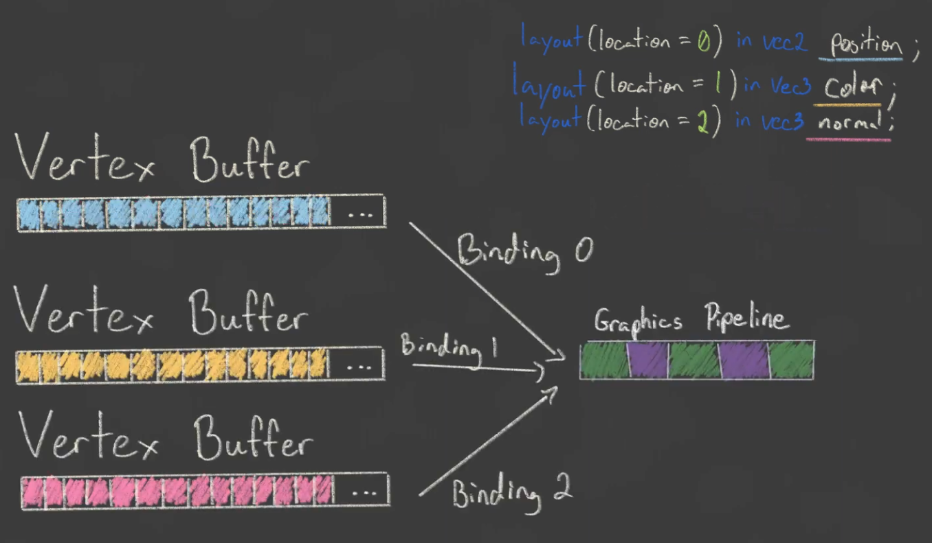 .
.
-
One binding per attribute.
-
-
One binding or many bindings? It doesn't matter that much. In some cases one is better, etc, don't worry too much about it.
Vertex Input Binding / Vertex Buffer
-
Tell Vulkan how to pass this data format to the vertex shader once it's been uploaded into GPU memory
-
A vertex binding describes at which rate to load data from memory throughout the vertices.
-
It specifies the number of bytes between data entries and whether to move to the next data entry after each vertex or after each instance.
-
VkVertexInputBindingDescription.-
binding-
Specifies the index of the binding in the array of bindings.
-
-
stride-
Specifies the number of bytes from one entry to the next.
-
-
inputRate-
VERTEX_INPUT_RATE_VERTEX-
Move to the next data entry after each vertex.
-
-
VERTEX_INPUT_RATE_INSTANCE-
Move to the next data entry after each instance.
-
-
We're not going to use instanced rendering, so we'll stick to per-vertex data.
-
-
-
VkVertexInputAttributeDescription-
Describes how to handle vertex input.
-
An attribute description struct describes how to extract a vertex attribute from a chunk of vertex data originating from a binding description.
-
We have two attributes, position and color, so we need two attribute description structs.
-
binding-
Tells Vulkan from which binding the per-vertex data comes.
-
-
location-
References the
locationdirective of the input in the vertex shader.-
The input in the vertex shader with location
0is the position, which has two 32-bit float components.
-
-
-
format-
Describes the type of data for the attribute.
-
Implicitly defines the byte size of attribute data.
-
A bit confusingly, the formats are specified using the same enumeration as color formats.
-
The following shader types and formats are commonly used together:
-
float:FORMAT_R32_SFLOAT -
vec2:FORMAT_R32G32_SFLOAT -
vec3:FORMAT_R32G32B32_SFLOAT -
vec4:FORMAT_R32G32B32A32_SFLOAT
-
-
As you can see, you should use the format where the amount of color channels matches the number of components in the shader data type.
-
It is allowed to use more channels than the number of components in the shader, but they will be silently discarded.
-
If the number of channels is lower than the number of components, then the BGA components will use default values of
(0, 0, 1).
-
-
The color type (
SFLOAT,UINT,SINT) and bit width should also match the type of the shader input. See the following examples:-
ivec2:FORMAT_R32G32_SINT, a 2-component vector of 32-bit signed integers -
uvec4:FORMAT_R32G32B32A32_UINT, a 4-component vector of 32-bit unsigned integers -
double:FORMAT_R64_SFLOAT, a double-precision (64-bit) float
-
-
-
offset-
Specifies the number of bytes since the start of the per-vertex data to read from.
-
-
-
Graphics Pipeline Vertex Input Binding :
-
For the following vertices:
Vertex :: struct { pos: eng.Vec2, color: eng.Vec3, } vertices := [?]Vertex{ { { 0.0, -0.5 }, { 1.0, 0.0, 0.0 } }, { { 0.5, 0.5 }, { 0.0, 1.0, 0.0 } }, { { -0.5, 0.5 }, { 0.0, 0.0, 1.0 } }, } -
We setup this in the Graphics Pipeline creation:
vertex_binding_descriptor := vk.VertexInputBindingDescription{ binding = 0, stride = size_of(Vertex), inputRate = .VERTEX, } vertex_attribute_descriptor := [?]vk.VertexInputAttributeDescription{ { binding = 0, location = 0, format = .R32G32_SFLOAT, offset = cast(u32)offset_of(Vertex, pos), }, { binding = 0, location = 1, format = .R32G32B32_SFLOAT, offset = cast(u32)offset_of(Vertex, color), }, } vertex_input_create_info := vk.PipelineVertexInputStateCreateInfo { sType = .PIPELINE_VERTEX_INPUT_STATE_CREATE_INFO, vertexBindingDescriptionCount = 1, pVertexBindingDescriptions = &vertex_binding_descriptor, vertexAttributeDescriptionCount = len(vertex_attribute_descriptor), pVertexAttributeDescriptions = &vertex_attribute_descriptor[0], } -
The pipeline is now ready to accept vertex data in the format of the
verticescontainer and pass it on to our vertex shader.
-
-
Vertex Buffer :
-
If you run the program now with validation layers enabled, you'll see that it complains that there is no vertex buffer bound to the binding.
-
The next step is to create a vertex buffer and move the vertex data to it so the GPU is able to access it.
-
Creating :
-
Follow the tutorial for creating a buffer, specifying
BUFFER_USAGE_VERTEX_BUFFERas theBufferCreateInfousage.
-
-
Index Buffer
-
Motivation :
-
Drawing a rectangle takes two triangles, which means that we need a vertex buffer with six vertices. The problem is that the data of two vertices needs to be duplicated, resulting in redundancies.
-
The solution to this problem is to use an index buffer.
-
An index buffer is essentially an array of pointers into the vertex buffer.
-
It allows you to reorder the vertex data, and reuse existing data for multiple vertices.
-
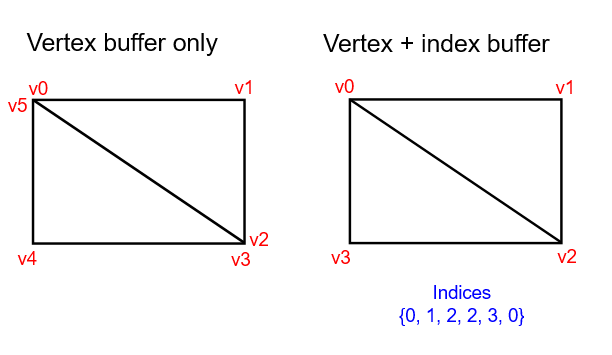 .
.
-
The first three indices define the upper-right triangle, and the last three indices define the vertices for the bottom-left triangle.
-
-
It is possible to use either
uint16_toruint32_tfor your index buffer depending on the number of entries invertices. We can stick touint16_tfor now because we’re using less than 65535 unique vertices. -
Just like the vertex data, the indices need to be uploaded into a
VkBufferfor the GPU to be able to access them.
-
-
Creating :
-
Follow the tutorial for creating a buffer, specifying
BUFFER_USAGE_INDEX_BUFFERas theBufferCreateInfousage.
-
-
Using :
-
We first need to bind the index buffer, just like we did for the vertex buffer.
-
The difference is that you can only have a single index buffer. It’s unfortunately not possible to use different indices for each vertex attribute, so we do still have to completely duplicate vertex data even if just one attribute varies.
-
An index buffer is bound with
vkCmdBindIndexBufferwhich has the index buffer, a byte offset into it, and the type of index data as parameters.-
As mentioned before, the possible types are
INDEX_TYPE_UINT16andINDEX_TYPE_UINT32.
-
-
Just binding an index buffer doesn’t change anything yet, we also need to change the drawing command to tell Vulkan to use the index buffer.
-
Remove the
vkCmdDrawline and replace it withvkCmdDrawIndexed.
-
Push Constants
-
A Push Constant is a small bank of values accessible in shaders.
-
These are designed for small amount (a few dwords) of high frequency data to be updated per-recording of the command buffer.
-
So that the shader can understand where this data will be sent, we specify a special push constants
<layout>in our shader code.
layout(push_constant) uniform MeshData {
    mat4 model;
} mesh_data;
-
Choosing to use Push Constants :
-
In early implementations of Vulkan on Arm Mali, this was usually the fastest way of pushing data to your shaders. In more recent times, we have observed on Mali devices that overall they can be slower. If performance is something you are trying to maximise on Mali devices, descriptor sets may be the way to go. However, other devices may still favour push constants.
-
Having said this, descriptor sets are one of the more complex features of Vulkan, making the convenience of push constants still worth considering as a go-to method, especially if working with trivial data.
-
-
Limits :
-
maxPushConstantsSize-
guaranteed at least
128bytes on all devices. -
If you're using Vulkan 1.4 the minimum was increased to 256.
-
-
Offsets
-
 .
.
-
Ex1 :
layout(push_constant, std430) uniform pc {
    layout(offset = 32) vec4 data;
};

layout(location = 0) out vec4 outColor;

void main() {
   outColor = data;
}
VkPushConstantRange range = {}; range.stageFlags = SHADER_STAGE_FRAGMENT; range.offset = 32; range.size = 16;
Updating
-
Ex1 :
-
Push constants can be incrementally updated over the course of a command buffer.
// vkBeginCommandBuffer() vkCmdBindPipeline(); vkCmdPushConstants(offset: 0, size: 16, value = [0, 0, 0, 0]); vkCmdDraw(); // values = [0, 0, 0, 0] vkCmdPushConstants(offset: 4, size: 8, value = [1 ,1]); vkCmdDraw(); // values = [0, 1, 1, 0] vkCmdPushConstants(offset: 8, size: 8, value = [2, 2]); vkCmdDraw(); // values = [0, 1, 2, 2] // vkEndCommandBuffer()-
Interesting how old values are kept. Values that were not changed are preserved.
-
Lifetime
-
vkCmdPushConstantsis tied to theVkPipelineLayoutusage and therefore why they must match before a call to a command such asvkCmdDraw(). -
Because push constants are not tied to descriptors, the use of
vkCmdBindDescriptorSetshas no effect on the lifetime or pipeline layout compatibility of push constants. -
The same way it is possible to bind descriptor sets that are never used by the shader, the same is true for push constants.
CPU Performance
-
Push one struct once per draw instead of many separate vkCmdPushConstants calls (one call writing a small struct is far cheaper).
-
Many small state changes cause the driver to update internal tables, validate, or patch commands — that’s CPU work and cannot be avoided without batching.
-
Observations :
-
5 push calls were taking 7.65us. I groupped all them in 1 single push call, now taking 3.08us.
-
This was substancial, as at the time I was issuing this push calls hundreds of time per frame; I later reduced this number, but anyway, could be significant.
-
Descriptors Sets
About
-
VkDescriptorSet -
One Descriptor -> One Resource.
-
They are always organized in Descriptor Sets.
-
One or more descriptors contained.
-
Combine descriptors which are used in conjunction.
-
-
A handle or pointer into a resource.
-
Note that is not just a pointer, but a pointer + metadata.
-
-
A core mechanism used to bind resources to shaders.
-
Holds the binding information that connects shader inputs to data such as
VkBufferresources andVkImagetextures. -
Think of it as a set of GPU-side pointers that you bind once.
-
The internal representation of a descriptor set is whatever the driver wants it to be.
-
Content :
-
Where to find a Resource.
-
Usage type of a Resource.
-
Offsets, sometimes.
-
Some metadata, sometimes.
-
-
Example :
-
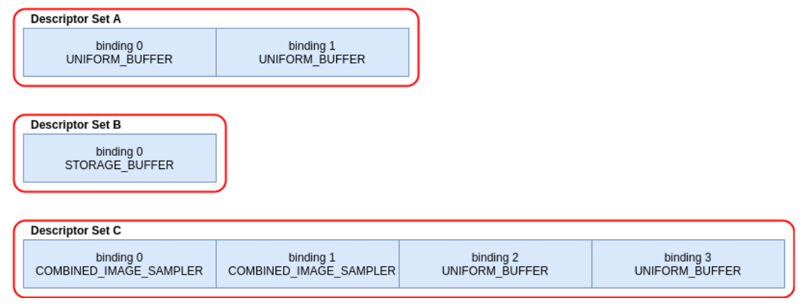 .
.
// Note - only set 0 and 2 are used in this shader layout(set = 0, binding = 0) uniform sampler2D myTextureSampler; layout(set = 0, binding = 2) uniform uniformBuffer0 { float someData; } ubo_0; layout(set = 0, binding = 3) uniform uniformBuffer1 { float moreData; } ubo_1; layout(set = 2, binding = 0) buffer storageBuffer { float myResults; } ssbo; -
-
API :
-
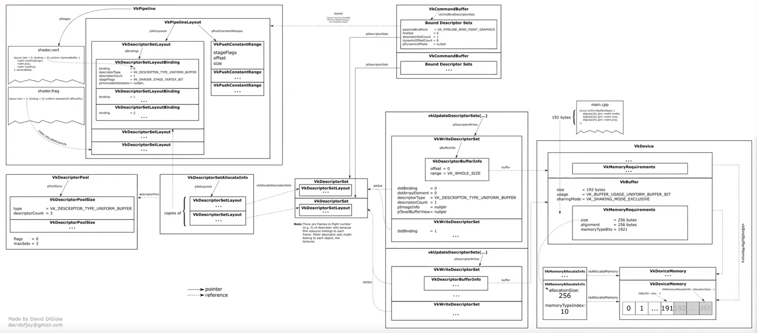 .
.
-
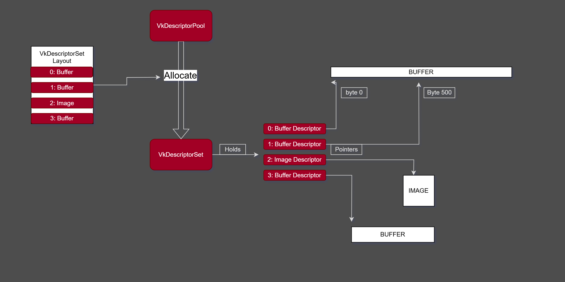 .
.
-
-
Limits :
-
maxBoundDescriptorSets -
Per stage limit
-
maxPerStageDescriptorSamplers -
maxPerStageDescriptorUniformBuffers -
maxPerStageDescriptorStorageBuffers -
maxPerStageDescriptorSampledImages -
maxPerStageDescriptorStorageImages -
maxPerStageDescriptorInputAttachments -
Per type limit
-
maxPerStageResources -
maxDescriptorSetSamplers -
maxDescriptorSetUniformBuffers -
maxDescriptorSetUniformBuffersDynamic -
maxDescriptorSetStorageBuffers -
maxDescriptorSetStorageBuffersDynamic -
maxDescriptorSetSampledImages -
maxDescriptorSetStorageImages -
maxDescriptorSetInputAttachments -
VkPhysicalDeviceDescriptorIndexingPropertiesif using Descriptor Indexing -
VkPhysicalDeviceInlineUniformBlockPropertiesEXTif using Inline Uniform Block
-
-
Visual explanation {0:00 -> 5:35} .
-
Nice.
-
The rest of the video is meh.
-
Difficulties
-
Problems :
-
"They are not bad but they very much force a specific rendering style: you have triple / quadrupled nested for loops, binding your things based on usage and then rebind descriptor sets as needed."
-
"Many of us are moving towards bindless rendering, where you just bind everything once in one big descriptor set, and then index into it at will; tho, Vulkan 1.0 does not greatly support, and also the descriptor count for it was quite low".
-
Cannot update descriptors after binding in a command buffer.
-
All descriptors must be valid, even if not used.
-
Descriptor arrays must be sampled uniformly.
-
Different invocations can’t use different indices.
-
Can sample “dynamically uniform”, e.g. runtime-based index.
-
-
Upper limit on descriptor counts.
-
Discourages GPU-driven rendering architectures.
-
Due to the need to set up descriptor sets per draw call it’s hard to adapt any of the aforementioned schemes to GPU-based culling or command submission.
-
-
-
Solutions :
-
Descriptor Indexing :
-
Available in 1.3, optional in 1.2, or
EXT_descriptor_indexing. -
Update descriptors after binding.
-
Update unused descriptors.
-
Relax requirement that all descriptors must be valid, even if unused.
-
Non-uniform array indexing.
-
-
Buffer Device Address :
-
Available in 1.3, optional in 1.2, or
KHR_buffer_device_address. -
Directly access buffers through addresses without a descriptor.
-
See [[#Physical Storage Buffer]] below.
-
-
Descriptor Buffers – EXT_descriptor_buffer :
-
Manage descriptors directly.
-
Similar to D3D12’s descriptor model.
-
-
Allocation
-
A scheme that works well is to use free lists of descriptor set pools; whenever you need a descriptor set pool, you allocate one from the free list and use it for subsequent descriptor set allocations in the current frame on the current thread. Once you run out of descriptor sets in the current pool, you allocate a new pool. Any pools that were used in a given frame need to be kept around; once the frame has finished rendering, as determined by the associated fence objects, the descriptor set pools can reset via
vkResetDescriptorPooland returned to free lists. While it’s possible to free individual descriptors from a pool viaDESCRIPTOR_POOL_CREATE_FREE_DESCRIPTOR_SET, this complicates the memory management on the driver side and is not recommended. -
When a descriptor set pool is created, application specifies the maximum number of descriptor sets allocated from it, as well as the maximum number of descriptors of each type that can be allocated from it. In Vulkan 1.1, the application doesn’t have to handle accounting for these limits – it can just call vkAllocateDescriptorSets and handle the error from that call by switching to a new descriptor set pool. Unfortunately, in Vulkan 1.0 without any extensions, it’s an error to call vkAllocateDescriptorSets if the pool does not have available space, so application must track the number of sets and descriptors of each type to know beforehand when to switch to a different pool.
-
Different pipeline objects may use different numbers of descriptors, which raises the question of pool configuration. A straightforward approach is to create all pools with the same configuration that uses the worst-case number of descriptors for each type – for example, if each set can use at most 16 texture and 8 buffer descriptors, one can allocate all pools with maxSets=1024, and pool sizes 16 1024 for texture descriptors and 8 1024 for buffer descriptors. This approach can work but in practice it can result in very significant memory waste for shaders with different descriptor count – you can’t allocate more than 1024 descriptor sets out of a pool with the aforementioned configuration, so if most of your pipeline objects use 4 textures, you’ll be wasting 75% of texture descriptor memory.
-
Strategies :
-
Two alternatives that provide a better balance memory use:
-
Measure an average number of descriptors used in a shader pipeline per type for a characteristic scene and allocate pool sizes accordingly. For example, if in a given scene we need 3000 descriptor sets, 13400 texture descriptors, and 1700 buffer descriptors, then the average number of descriptors per set is 4.47 textures (rounded up to 5) and 0.57 buffers (rounded up to 1), so a reasonable configuration of a pool is maxSets=1024, 5*1024 texture descriptors, 1024 buffer descriptors. When a pool is out of descriptors of a given type, we allocate a new one – so this scheme is guaranteed to work and should be reasonably efficient on average.
-
Group shader pipeline objects into size classes, approximating common patterns of descriptor use, and pick descriptor set pools using the appropriate size class. This is an extension of the scheme described above to more than one size class. For example, it’s typical to have large numbers of shadow/depth prepass draw calls, and large numbers of regular draw calls in a scene – but these two groups have different numbers of required descriptors, with shadow draw calls typically requiring 0 to 1 textures per set and 0 to 1 buffers when dynamic buffer offsets are used. To optimize memory use, it’s more appropriate to allocate descriptor set pools separately for shadow/depth and other draw calls. Similarly to general-purpose allocators that can have size classes that are optimal for a given application, this can still be managed in a lower-level descriptor set management layer as long as it’s configured with application specific descriptor set usages beforehand.
-
Implementation
-
Descriptors are like pointers, so as any pointer they need to allocate space to live ahead of time.
-
How many :
-
Its possible to have 1 very big descriptor pool that handles the entire engine, but that means we need to know what descriptors we will be using for everything ahead of time.
-
That can be very tricky to do at scale. Instead, we will keep it simpler, and we will have multiple descriptor pools for different parts of the project , and try to be more accurate with them.
-
I don't know what that actually means in practice.
-
-
-
-
Maintains a pool of descriptors, from which descriptor sets are allocated.
-
Descriptor pools are externally synchronized, meaning that the application must not allocate and/or free descriptor sets from the same pool in multiple threads simultaneously.
-
They are very opaque.
-
-
Contains a type of descriptor (same
VkDescriptorTypeas on the bindings above ), alongside a ratio to multiply themaxSetsparameter is. -
This lets us directly control how big the pool is going to be.
maxSetscontrols how manyVkDescriptorSetswe can create from the pool in total, and the pool sizes give how many individual bindings of a given type are owned. -
flags.-
Is a bitmask of VkDescriptorPoolCreateFlagBits specifying certain supported operations on the pool.
-
DESCRIPTOR_POOL_CREATE_FREE_DESCRIPTOR_SET-
Determines if individual descriptor sets can be freed or not:
-
We're not going to touch the descriptor set after creating it, so we don't need this flag. You can leave
flagsto its default value of0.
-
-
DESCRIPTOR_POOL_CREATE_UPDATE_AFTER_BIND-
Descriptor pool creation may fail with the error
ERROR_FRAGMENTATIONif the total number of descriptors across all pools (including this one) created with this bit set exceedsmaxUpdateAfterBindDescriptorsInAllPools, or if fragmentation of the underlying hardware resources occurs.
-
-
-
maxSets-
Is the maximum number of descriptor sets that can be allocated from the pool.
-
-
poolSizeCount-
Is the number of elements in
pPoolSizes.
-
-
pPoolSizes-
Is a pointer to an array of VkDescriptorPoolSize structures, each containing a descriptor type and number of descriptors of that type to be allocated in the pool.
-
If multiple
VkDescriptorPoolSizestructures containing the same descriptor type appear in thepPoolSizesarray then the pool will be created with enough storage for the total number of descriptors of each type. -
-
type-
Is the type of descriptor.
-
-
descriptorCount-
Is the number of descriptors of that type to allocate. If
typeisDESCRIPTOR_TYPE_INLINE_UNIFORM_BLOCKthendescriptorCountis the number of bytes to allocate for descriptors of this type.
-
-
-
-
-
-
-
descriptorPool-
Is the pool which the sets will be allocated from.
-
-
descriptorSetCount-
Determines the number of descriptor sets to be allocated from the pool.
-
-
pSetLayouts-
Is a pointer to an array of descriptor set layouts, with each member specifying how the corresponding descriptor set is allocated.
-
-
-
-
The allocated descriptor sets are returned in
pDescriptorSets. -
When a descriptor set is allocated, the initial state is largely uninitialized and all descriptors are undefined, with the exception that samplers with a non-null
pImmutableSamplersare initialized on allocation. -
Descriptors also become undefined if the underlying resource or view object is destroyed.
-
Descriptor sets containing undefined descriptors can still be bound and used, subject to the following conditions:
-
For descriptor set bindings created with the
PARTIALLY_BOUNDbit set:-
All descriptors in that binding that are dynamically used must have been populated before the descriptor set is consumed .
-
-
For descriptor set bindings created without the
PARTIALLY_BOUNDbit set:-
All descriptors in that binding that are statically used must have been populated before the descriptor set is consumed .
-
-
Descriptor bindings with descriptor type of
DESCRIPTOR_TYPE_INLINE_UNIFORM_BLOCKcan be undefined when the descriptor set is consumed ; though values in that block will be undefined. -
Entries that are not used by a pipeline can have undefined descriptors.
-
-
pAllocateInfo-
Is a pointer to a VkDescriptorSetAllocateInfo structure describing parameters of the allocation.
-
-
pDescriptorSets-
Is a pointer to an array of VkDescriptorSet handles in which the resulting descriptor set objects are returned.
-
-
-
Multithreading :
-
Descriptor pools are externally synchronized, meaning that the application must not allocate and/or free descriptor sets from the same pool in multiple threads simultaneously.
-
Command Pools are used to allocate, free, reset, and update descriptor sets. By creating multiple descriptor pools, each application host thread is able to manage a descriptor set in each descriptor pool at the same time.
-
Best Practices
-
Don’t allocate descriptor sets if nothing in the set changed. In the model with slots that are shared between different stages, this can mean that if no textures are set between two draw calls, you don’t need to allocate the descriptor set with texture descriptors.
-
Don't allocate descriptor sets from descriptor pools on performance critical code paths.
-
Don't allocate, free or update descriptor sets every frame, unless it is necessary.
-
Don't set
DESCRIPTOR_POOL_CREATE_FREE_DESCRIPTOR_SETif you do not need to free individual descriptor sets.-
Setting
DESCRIPTOR_POOL_CREATE_FREE_DESCRIPTOR_SETmay prevent the implementation from using a simpler (and faster) allocator.
-
Descriptor Types
Overview
-
For buffers, application must choose between uniform and storage buffers, and whether to use dynamic offsets or not. Uniform buffers have a limit on the maximum addressable size – on desktop hardware, you get up to 64 KB of data, however on mobile hardware some GPUs only provide 16 KB of data (which is also the guaranteed minimum by the specification). The buffer resource can be larger than that, but shader can only access this much data through one descriptor.
-
On some hardware, there is no difference in access speed between uniform and storage buffers, however for other hardware depending on the access pattern uniform buffers can be significantly faster. Prefer uniform buffers for small to medium sized data especially if the access pattern is fixed (e.g. for a buffer with material or scene constants). Storage buffers are more appropriate when you need large arrays of data that need to be larger than the uniform buffer limit and are indexed dynamically in the shader.
-
For textures, if filtering is required, there is a choice of combined image/sampler descriptor (where, like in OpenGL, descriptor specifies both the source of the texture data, and the filtering/addressing properties), separate image and sampler descriptors (which maps better to Direct3D 11 model), and image descriptor with an immutable sampler descriptor, where the sampler properties must be specified when pipeline object is created.
-
The relative performance of these methods is highly dependent on the usage pattern; however, in general immutable descriptors map better to the recommended usage model in other newer APIs like Direct3D 12, and give driver more freedom to optimize the shader. This does alter renderer design to a certain extent, making it necessary to implement certain dynamic portions of the sampler state, like per-texture LOD bias for texture fade-in during streaming, using shader ALU instructions.
Storage Images
-
DESCRIPTOR_TYPE_STORAGE_IMAGE -
Is a descriptor type that allows shaders to read from and write to an image without using a fixed-function graphics pipeline.
-
This is particularly useful for compute shaders and advanced rendering techniques.
// FORMAT_R32_UINT
layout(set = 0, binding = 0, r32ui) uniform uimage2D storageImage;

// example usage for reading and writing in GLSL
const uvec4 texel = imageLoad(storageImage, ivec2(0, 0));
imageStore(storageImage, ivec2(1, 1), texel);
-
Use cases :
-
Image Processing :
-
Storage images are ideal for image processing tasks like filters, blurs, and other post-processing effects.
-
-
Sampler
-
DESCRIPTOR_TYPE_SAMPLERandDESCRIPTOR_TYPE_SAMPLED_IMAGE.
layout(set = 0, binding = 0) uniform sampler samplerDescriptor;
layout(set = 0, binding = 1) uniform texture2D sampledImage;

// example usage of using texture() in GLSL
vec4 data = texture(sampler2D(sampledImage,  samplerDescriptor), vec2(0.0, 0.0));
Combined Image Sampler
-
DESCRIPTOR_TYPE_COMBINED_IMAGE_SAMPLER -
On some implementations, it may be more efficient to sample from an image using a combination of sampler and sampled image that are stored together in the descriptor set in a combined descriptor.
layout(set = 0, binding = 0) uniform sampler2D combinedImageSampler;

// example usage of using texture() in GLSL
vec4 data = texture(combinedImageSampler, vec2(0.0, 0.0));
Uniform Buffer / UBO (Uniform Buffer Object)
-
DESCRIPTOR_TYPE_UNIFORM_BUFFER -
Uniform buffers can also have dynamic offsets at bind time (
DESCRIPTOR_TYPE_UNIFORM_BUFFER_DYNAMIC).
layout(set = 0, binding = 0) uniform uniformBuffer {
    float a;
    int b;
} ubo;

// example of reading from UBO in GLSL
int x = ubo.b + 1;
vec3 y = vec3(ubo.a);
-
Uniform Buffers commonly use
std140layout (strict alignment rules, predictable padding).-
Source: ChatGPT. I want to confirm.
-
/* UBO: small read-only data (std140) */
layout(set = 0, binding = 0, std140) uniform SceneParams {
    mat4 viewProj;
    vec4 lightPos;
    float time;
} scene;
-
UBO (Uniform Buffer Object) :
-
“Uniform buffer object” is more of an OpenGL-era name, but some Vulkan tutorials and developers still use it informally to mean the same thing — the buffer that holds uniform data.
-
Storage Buffer / SSBO (Shader Storage Buffer Object)
-
DESCRIPTOR_TYPE_STORAGE_BUFFER -
GLSL uses distinct address spaces:
uniform→ UBO,buffer→ SSBO. -
Use
std430layout by default (tighter packing, fewer padding requirements). -
SSBO (Shader Storage Buffer Object) is a OpenGL term.
// Implicit std430 (default)
layout(set = 0, binding = 0) buffer storageBuffer {
    float a;
    int b;
} ssbo;

// Explicit std430
layout(set = 0, binding = 1, std430) buffer ParticleData {
    vec4 pos[];
} particles;

// Reading and writing to a SSBO in GLSL
ssbo.a = ssbo.a + 1.0;
ssbo.b = ssbo.b + 1;
-
BufferBlockandUniformwould have been seen prior toKHR_storage_buffer_storage_class. -
Storage buffers can also have dynamic offsets at bind time
DESCRIPTOR_TYPE_STORAGE_BUFFER_DYNAMIC. -
Why SSBO for dynamic arrays :
-
std430allows tight packing and runtime-sized arrays(T data[]), which is ideal for dynamic-length storage. -
SSBOs allow arbitrary indexing, read/write, and atomics.
-
maxStorageBufferRange is usually much larger than
maxUniformBufferRange. -
You can use
*_DYNAMICdescriptors to bind multiple subranges of one large backing buffer cheaply.
-
-
Many arrays :
-
A buffer block may contain multiple arrays, but only the last member of the block may be a runtime-sized (unsized) array
T x[]. All other arrays must be fixed-size (compile-time constant) or you must implement sizing/offsets yourself.-
This is invalid , even with descriptor indexing:
layout(std430, set = 0, binding = 0) buffer FixedArrays { vec4 A[]; vec2 B[]; mat4 C[]; some_struct D[]; } fixedArrays; -
-
Use a
uint x[]:-
32-bit words; simplest and portable.
-
This is effectively an untyped byte/word blob stored in the SSBO and you manually reinterpret (cast) it in the shader
layout(std430, set = 0, binding = 0) buffer PackedBytes { uint countA; // number of A elements uint offsetA; // offset into data[] in uint words uint countB; uint offsetB; // offset into data[] in uint words uint countC; uint offsetC; uint data[]; // payload in 32-bit words } pb; // helpers float readFloat(uint baseWordIndex) { return uintBitsToFloat(pb.data[baseWordIndex]); } vec2 readVec2(uint baseWordIndex) { return vec2( uintBitsToFloat(pb.data[baseWordIndex + 0]), uintBitsToFloat(pb.data[baseWordIndex + 1]) ); } vec3 readVec3(uint baseWordIndex) { return vec3( uintBitsToFloat(pb.data[baseWordIndex + 0]), uintBitsToFloat(pb.data[baseWordIndex + 1]), uintBitsToFloat(pb.data[baseWordIndex + 2]) ); } vec4 readVec4(uint baseWordIndex) { return vec4( uintBitsToFloat(pb.data[baseWordIndex + 0]), uintBitsToFloat(pb.data[baseWordIndex + 1]), uintBitsToFloat(pb.data[baseWordIndex + 2]), uintBitsToFloat(pb.data[baseWordIndex + 3]) ); } mat4 readMat4(uint baseWordIndex) { // mat4 stored column-major as 16 floats (4 columns of vec4) return mat4( readVec4(baseWordIndex + 0), readVec4(baseWordIndex + 4), readVec4(baseWordIndex + 8), readVec4(baseWordIndex + 12) ); } -
-
Use a
vec4 x[]:-
128-bit blocks; simpler alignment for vec4/mat4 data.
// Pack everything into vec4 blocks for simple alignment layout(std430, set = 0, binding = 0) buffer Packed { uint countA; uint offsetA; // in vec4-blocks uint countB; uint offsetB; // in vec4-blocks uint countC; uint offsetC; // in vec4-blocks uint countD; uint offsetD; // in vec4-blocks vec4 blocks[]; // single runtime-sized array (last member) } packed; // helpers vec4 getA(uint i) { return packed.blocks[packed.offsetA + i]; } vec2 getB(uint i) { return packed.blocks[packed.offsetB + i].xy; // we store each B in one vec4 block } mat4 getC(uint i) { uint base = packed.offsetC + i * 4; // mat4 occupies 4 vec4 blocks return mat4(packed.blocks[base + 0], packed.blocks[base + 1], packed.blocks[base + 2], packed.blocks[base + 3]); } // for some_struct D that we store as 1 vec4 per element: some_struct getD(uint i) { vec4 v = packed.blocks[packed.offsetD + i]; // decode v -> some_struct fields } -
-
Use many SSBOs:
layout(std430, set=0, binding=0) buffer BufA { vec4 A[]; } bufA;
layout(std430, set=0, binding=1) buffer BufB { vec2 B[]; } bufB;
layout(std430, set=0, binding=2) buffer BufC { mat4 C[]; } bufC;
layout(std430, set=0, binding=3) buffer BufD { some_struct D[]; } bufD;
-
Texel Buffer
-
Texel buffers are a way to access buffer data with texture-like operations in shaders.
-
-
The format specified in the shader (SPIR-V Image Format) must exactly match the format used when creating the VkImageView (Vulkan Format).
-
Require exact format matching between the shader and the view. The views must always match the shader exactly.
-
-
Uniform Texel Buffer :
-
DESCRIPTOR_TYPE_UNIFORM_TEXEL_BUFFER -
Read-only access.
layout(set = 0, binding = 0) uniform textureBuffer uniformTexelBuffer; // example of reading texel buffer in GLSL vec4 data = texelFetch(uniformTexelBuffer, 0);-
Use cases :
-
Lookup Tables :
-
Uniform texel buffers are useful for implementing lookup tables that need to be accessed with texture-like operations.
-
-
-
-
Storage Texel Buffer :
-
DESCRIPTOR_TYPE_STORAGE_TEXEL_BUFFER -
Read-write access.
// FORMAT_R8G8B8A8_UINT layout(set = 0, binding = 0, rgba8ui) uniform uimageBuffer storageTexelBuffer; // example of reading and writing texel buffer in GLSL int offset = int(gl_GlobalInvocationID.x); vec4 data = imageLoad(storageTexelBuffer, offset); imageStore(storageTexelBuffer, offset, uvec4(0));-
Use cases :
-
Particle Systems :
-
Storage texel buffers can be used to store and update particle data in a compute shader, which can then be read by a vertex shader for rendering.
-
-
-
Input Attachment
-
DESCRIPTOR_TYPE_INPUT_ATTACHMENT
layout (input_attachment_index = 0, set = 0, binding = 0) uniform subpassInput inputAttachment;

// example loading the attachment data in GLSL
vec4 data = subpassLoad(inputAttachment);
Updates
Implementation
-
A Descriptor Set, even though created and allocated, is still empty. We need to fill it up with data.
-
Updates must happen outside of a command record and execution.
-
No update after
vkCmdBindDescriptorSets(). -
Usually you update before
vkBeginCommandBuffer()or after thevkQueueSubmit()(if we know the sync is done for cmd).
-
-
If using Descriptor Indexing :
-
Descriptors can be updated after binding in command buffers.
-
Command buffer execution will use most recent updates.
-
-
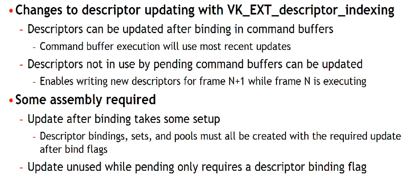 .
.
-
-
-
dstSet-
Is the destination descriptor set to update.
-
-
dstBinding-
Is the descriptor binding within that set.
-
-
dstArrayElement-
Remember that descriptors can be arrays, so we also need to specify the first index in the array that we want to update.
-
If not using an array, the index is simply
0. -
Is the starting element in that array.
-
If the descriptor binding identified by
dstSetanddstBindinghas a descriptor type ofDESCRIPTOR_TYPE_INLINE_UNIFORM_BLOCKthendstArrayElementspecifies the starting byte offset within the binding.
-
-
descriptorCount-
It's a descriptor count, not a descriptor SET count!!
-
Is the number of descriptors to update.
-
If the descriptor binding identified by
dstSetanddstBindinghas a descriptor type ofDESCRIPTOR_TYPE_INLINE_UNIFORM_BLOCK, thendescriptorCountspecifies the number of bytes to update. -
Otherwise,
descriptorCountis one of-
the number of elements in
pImageInfo -
the number of elements in
pBufferInfo -
the number of elements in
pTexelBufferView -
a value matching the
dataSizemember of a VkWriteDescriptorSetInlineUniformBlock structure in thepNextchain -
a value matching the
accelerationStructureCountof a VkWriteDescriptorSetAccelerationStructureKHR or VkWriteDescriptorSetAccelerationStructureNV structure in thepNextchain -
a value matching the
descriptorCountof a VkWriteDescriptorSetTensorARM structure in thepNextchain
-
-
-
descriptorType-
We need to specify the type of descriptor again
-
Is a VkDescriptorType specifying the type of each descriptor in
pImageInfo,pBufferInfo, orpTexelBufferView. -
It must be the same type as the
descriptorTypespecified inVkDescriptorSetLayoutBindingfordstSetatdstBinding, except ifVkDescriptorSetLayoutBindingfordstSetatdstBindingis equal toDESCRIPTOR_TYPE_MUTABLE_EXT. -
The type of the descriptor also controls which array the descriptors are taken from.
-
-
pBufferInfo-
Is a pointer to an array of VkDescriptorBufferInfo structures or is ignored, as described below.
-
-
Structure specifying descriptor buffer information
-
Specifies the buffer and the region within it that contains the data for the descriptor.
-
buffer-
Is the buffer resource or NULL_HANDLE .
-
-
offset-
Is the offset in bytes from the start of
buffer. -
Access to buffer memory via this descriptor uses addressing that is relative to this starting offset.
-
For
DESCRIPTOR_TYPE_UNIFORM_BUFFER_DYNAMICandDESCRIPTOR_TYPE_STORAGE_BUFFER_DYNAMICdescriptor types:-
offsetis the base offset from which the dynamic offset is applied.
-
-
-
range-
Is the size in bytes that is used for this descriptor update, or
WHOLE_SIZEto use the range fromoffsetto the end of the buffer.-
When
rangeisWHOLE_SIZEthe effective range is calculated at vkUpdateDescriptorSets by taking the size ofbufferminus theoffset.
-
-
For
DESCRIPTOR_TYPE_UNIFORM_BUFFER_DYNAMICandDESCRIPTOR_TYPE_STORAGE_BUFFER_DYNAMICdescriptor types:-
rangeis the static size used for all dynamic offsets.
-
-
-
-
-
pImageInfo-
Is a pointer to an array of VkDescriptorImageInfo structures or is ignored, as described below.
-
-
imageLayout-
Is the layout that the image subresources accessible from
imageViewwill be in at the time this descriptor is accessed. -
Is used in descriptor updates for types
DESCRIPTOR_TYPE_SAMPLED_IMAGE,DESCRIPTOR_TYPE_STORAGE_IMAGE,DESCRIPTOR_TYPE_COMBINED_IMAGE_SAMPLER, andDESCRIPTOR_TYPE_INPUT_ATTACHMENT.
-
-
imageView-
Is an image view handle or NULL_HANDLE .
-
Is used in descriptor updates for types
DESCRIPTOR_TYPE_SAMPLED_IMAGE,DESCRIPTOR_TYPE_STORAGE_IMAGE,DESCRIPTOR_TYPE_COMBINED_IMAGE_SAMPLER, andDESCRIPTOR_TYPE_INPUT_ATTACHMENT.
-
-
sampler-
Is a sampler handle.
-
Is used in descriptor updates for types
DESCRIPTOR_TYPE_SAMPLERandDESCRIPTOR_TYPE_COMBINED_IMAGE_SAMPLERif the binding being updated does not use immutable samplers.
-
-
-
-
pTexelBufferView-
Is a pointer to an array of VkBufferView handles as described in the Buffer Views section or is ignored, as described below.
-
-
-
-
descriptorWriteCount-
Is the number of elements in the
pDescriptorWritesarray.
-
-
pDescriptorWrites-
Is a pointer to an array of VkWriteDescriptorSet structures describing the descriptor sets to write to.
-
-
descriptorCopyCount-
Is the number of elements in the
pDescriptorCopiesarray.
-
-
pDescriptorCopies-
Is a pointer to an array of VkCopyDescriptorSet structures describing the descriptor sets to copy between.
-
-
Best Practices
-
Don’t update descriptor sets if nothing in the set changed. In the model with slots that are shared between different stages, this can mean that if no textures are set between two draw calls, you don’t need to update the descriptor set with texture descriptors.
-
When rendering dynamic objects the application will need to push some amount of per-object data to the GPU, such as the MVP matrix. This data may not fit into the push constant limit for the device, so it becomes necessary to send it to the GPU by putting it into a
VkBufferand binding a descriptor set that points to it. -
Materials also need their own descriptor sets, which point to the textures they use. We can either bind per-material and per-object descriptor sets separately or collate them into a single set. Either way, complex applications will have a large amount of descriptor sets that may need to change on the fly, for example due to textures being streamed in or out.
-
Not-good Solution: One or more pools per-frame, resetting the pool :
-
The simplest approach to circumvent the issue is to have one or more
VkDescriptorPools per frame, reset them at the beginning of the frame and allocate the required descriptor sets from it. This approach will consist of a vkResetDescriptorPool() call at the beginning, followed by a series of vkAllocateDescriptorSets() and vkUpdateDescriptorSets() to fill them with data. -
This is very useful for things like per-frame descriptors. That way we can have descriptors that are used just for one frame, allocated dynamically, and then before we start the frame we completely delete all of them in one go.
-
This is confirmed to be a fast path by GPU vendors, and recommended to use when you need to handle per-frame descriptor sets.
-
The issue is that these calls can add a significant overhead to the CPU frame time, especially on mobile. In the worst cases, for example calling vkUpdateDescriptorSets() for each draw call, the time it takes to update descriptors can be longer than the time of the draws themselves.
-
-
Solution: Caching descriptor sets :
-
A major way to reduce descriptor set updates is to re-use them as much as possible. Instead of calling vkResetDescriptorPool() every frame, the app will keep the
VkDescriptorSethandles stored with some caching mechanism to access them. -
The cache could be a hashmap with the contents of the descriptor set (images, buffers) as key. This approach is used in our framework by default. It is possible to remove another level of indirection by storing descriptor set handles directly in the materials and/or meshes.
-
Caching descriptor sets has a dramatic effect on frame time for our CPU-heavy scene.
-
In this game on a 2019 mobile phone it went from 44ms (23fps) to 27ms (37fps). This is a 38% decrease in frame time.
-
This system is reasonably easy to implement for a static scene, but it becomes harder when you need to delete descriptor sets. Complex engines may implement techniques to figure out which descriptor sets have not been accessed for a certain number of frames, so they can be removed from the map.
-
This may correspond to calling vkFreeDescriptorSets() , but this solution poses another issue: in order to free individual descriptor sets the pool has to be created with the
DESCRIPTOR_POOL_CREATE_FREE_DESCRIPTOR_SETflag. Mobile implementations may use a simpler allocator if that flag is not set, relying on the fact that pool memory will only be recycled in block. -
It is possible to avoid using that flag by updating descriptor sets instead of deleting them. The application can keep track of recycled descriptor sets and re-use one of them when a new one is requested.
-
-
Solution: One buffer per-frame :
-
We will now explore an alternative approach, that is complementary to descriptor caching in some way. Especially for applications in which descriptor caching is not quite feasible, buffer management is another lever for optimizing performance.
-
As discussed at the beginning, each rendered object will typically need some uniform data along with it, that needs to be pushed to the GPU somehow. A straightforward approach is to store a
VkBufferper object and update that data for each frame. -
This already poses an interesting question: is one buffer enough? The problem is that this data will change dynamically and will be in use by the GPU while the frame is in flight.
-
Since we do not want to flush the GPU pipeline between each frame, we will need to keep several copies of each buffer, one for each frame in flight.
-
Another similar option is to use just one buffer per object, but with a size equal to
num_frames * buffer_size, then offset it dynamically based on the frame index.-
For each frame, one buffer per object is created and filled with data. This means that we will have many descriptor sets to create, since every object will need one that points to its
VkBuffer. Furthermore, we will have to update many buffers separately, meaning we cannot control their memory layout and we might lose some optimization opportunities with caching.
-
-
We can address both problems by reverting the approach: instead of having a
VkBufferper object containing per-frame data, we will have aVkBufferper frame containing per-object data. The buffer will be cleared at the beginning of the frame, then each object will record its data and will receive a dynamic offset to be used at vkCmdBindDescriptorSets() time. -
With this approach we will need fewer descriptor sets, as more objects can share the same one: they will all reference the same
VkBuffer, but at different dynamic offsets. Furthermore, we can control the memory layout within the buffer. -
Using a single large
VkBufferin this case shows a performance improvement similar to descriptor set caching. -
For this relatively simple scene stacking the two approaches does not provide a further performance boost, but for a more complex case they do stack nicely:
-
Descriptor caching is necessary when the number of descriptor sets is not just due to
VkBuffers with uniform data, for example if the scene uses a large amount of materials/textures. -
Buffer management will help reduce the overall number of descriptor sets, thus cache pressure will be reduced and the cache itself will be smaller.
-
-
(2025-09-08)
-
I personally liked this technique much more than descriptor caching.
-
It sounds more concrete than fiddling with descriptor sets.
-
Reminds me of Buffer Device Address.
-
-
-
Do
-
Update already allocated but no longer referenced descriptor sets, instead of resetting descriptor pools and reallocating new descriptor sets.
-
Prefer reusing already allocated descriptor sets, and not updating them with the same information every time.
-
Consider caching your descriptor sets when feasible.
-
Consider using a single (or few)
VkBufferper frame with dynamic offsets. -
Batch calls to vkAllocateDescriptorSets if possible – on some drivers, each call has measurable overhead, so if you need to update multiple sets, allocating both in one call can be faster;
-
To update descriptor sets, either use vkUpdateDescriptorSets with descriptor write array, or use
vkUpdateDescriptorSetWithTemplatefrom Vulkan 1.1. Using the descriptor copy functionality ofvkUpdateDescriptorSetsis tempting with dynamic descriptor management for copying most descriptors out of a previously allocated array, but this can be slow on drivers that allocate descriptors out of write-combined memory. Descriptor templates can reduce the amount of work application needs to do to perform updates – since in this scheme you need to read descriptor information out of shadow state maintained by application, descriptor templates allow you to tell the driver the layout of your shadow state, making updates substantially faster on some drivers. -
Prefer dynamic uniform buffers to updating uniform buffer descriptors. Dynamic uniform buffers allow to specify offsets into buffer objects using pDynamicOffsets argument of vkCmdBindDescriptorSets without allocating and updating new descriptors. This works well with dynamic constant management where constants for draw calls are allocated out of large uniform buffers, substantially reduce CPU overhead, and can be more efficient on GPU. While on some GPUs the number of dynamic buffers must be kept small to avoid extra overhead in the driver, one or two dynamic uniform buffers should work well in this scheme on all architectures.
-
On some drivers, unfortunately the allocate & update path is not very optimal – on some mobile hardware, it may make sense to cache descriptor sets based on the descriptors they contain if they can be reused later in the frame.
-
Descriptor Set Layout
-
Contains the information about what that descriptor set holds.
-
Specifies the types of resources that are going to be accessed by the pipeline, just like a render pass specifies the types of attachments that will be accessed.
-
How many :
-
You need to specify a descriptor set layout for each descriptor set when creating the pipeline layout.
-
You can use this feature to put descriptors that vary per-object and descriptors that are shared into separate descriptor sets.
-
In that case, you avoid rebinding most of the descriptors across draw calls which are potentially more efficient.
-
-
Since the buffer structure is identical across frames, one layout suffices.
-
Create only 1 descriptor set layout, regardless of frames in-flight.
-
This layout defines the type of resource (e.g.,
VKDESCRIPTORTYPEUNIFORMBUFFER) and its binding point.
-
-
-
-
Opaque handle to a descriptor set layout object.
-
Is defined by an array of zero or more descriptor bindings.
-
Where it's used :
-
VkDescriptorSetLayoutBinding.-
Structure specifying a descriptor set layout binding.
-
Each individual descriptor binding is specified by a descriptor type, a count (array size) of the number of descriptors in the binding, a set of shader stages that can access the binding, and (if using immutable samplers) an array of sampler descriptors.
-
Bindings that are not specified have a
descriptorCountandstageFlagsof zero, and the value ofdescriptorTypeis undefined. -
binding-
Is the binding number of this entry and corresponds to a resource of the same binding number in the shader stages.
-
Used in the shader and the type of descriptor, which is a uniform buffer object.
-
-
descriptorType-
Is a VkDescriptorType specifying which type of resource descriptors are used for this binding.
-
-
descriptorCount-
Insight :
-
It's a descriptor count, not a descriptor SET count !! It's just to specify how many resources is expected to be in that binding.
-
It makes complete sense to be used for arrays.
-
Caio:
-
What happens if the values don't match? For example, trying to get the index 5 of the array, when the binding was described having
descriptorCount = 1?
-
-
Oni:
-
I don't know if this is specified. I guess it's only going to update the first element. So you're going to read bogus data. Maybe it changes between different drivers, no idea.
-
-
-
What value to use :
-
A MVP transformation is in a single uniform buffer, so we using a
descriptorCountof1. -
In other words, a whole struct counts as
1.
-
-
Is the number of descriptors contained in the binding, accessed in a shader as an array.
-
Except if
descriptorTypeisDESCRIPTOR_TYPE_INLINE_UNIFORM_BLOCKin which casedescriptorCountis the size in bytes of the inline uniform block.
-
-
If
descriptorCountis zero this binding entry is reserved and the resource must not be accessed from any stage via this binding within any pipeline using the set layout. -
It is possible for the shader variable to represent an array of uniform buffer objects, and this property specifies the number of values in the array.
-
Examples :
-
This could be used to specify a transformation for each of the bones in a skeleton for skeletal animation.
-
-
-
stageFlags-
Is a bitmask of VkShaderStageFlagBits specifying which pipeline shader stages can access a resource for this binding.
-
SHADER_STAGE_ALLis a shorthand specifying all defined shader stages, including any additional stages defined by extensions.
-
-
If a shader stage is not included in
stageFlags, then a resource must not be accessed from that stage via this binding within any pipeline using the set layout. -
Other than input attachments which are limited to the fragment shader, there are no limitations on what combinations of stages can use a descriptor binding, and in particular a binding can be used by both graphics stages and the compute stage.
-
-
pImmutableSamplers-
Affects initialization of samplers.
-
If
descriptorTypespecifies aDESCRIPTOR_TYPE_SAMPLERorDESCRIPTOR_TYPE_COMBINED_IMAGE_SAMPLERtype descriptor, thenpImmutableSamplerscan be used to initialize a set of immutable samplers . -
If
descriptorTypeis not one of these descriptor types, thenpImmutableSamplersis ignored . -
Immutable samplers are permanently bound into the set layout and must not be changed; updating a
DESCRIPTOR_TYPE_SAMPLERdescriptor with immutable samplers is not allowed and updates to aDESCRIPTOR_TYPE_COMBINED_IMAGE_SAMPLERdescriptor with immutable samplers does not modify the samplers (the image views are updated, but the sampler updates are ignored). -
If
pImmutableSamplersis notNULL, then it is a pointer to an array of sampler handles that will be copied into the set layout and used for the corresponding binding. Only the sampler handles are copied; the sampler objects must not be destroyed before the final use of the set layout and any descriptor pools and sets created using it. -
If
pImmutableSamplersisNULL, then the sampler slots are dynamic and sampler handles must be bound into descriptor sets using this layout. ]
-
-
-
VkDescriptorSetLayoutCreateInfo.-
pBindings-
A pointer to an array of
VkDescriptorSetLayoutBindingstructures.
-
-
bindingCount-
Is the number of elements in
pBindings.
-
-
flags-
Is a bitmask of VkDescriptorSetLayoutCreateFlagBits specifying options for descriptor set layout creation.
-
-
-
vkCreateDescriptorSetLayout().-
Create a new descriptor set layout.
-
pCreateInfo-
Is a pointer to a VkDescriptorSetLayoutCreateInfo structure specifying the state of the descriptor set layout object.
-
-
pAllocator-
Controls host memory allocation as described in the Memory Allocation chapter.
-
-
pSetLayout-
Is a pointer to a VkDescriptorSetLayout handle in which the resulting descriptor set layout object is returned.
-
-
-
-
-
Structure specifying the parameters of a newly created pipeline layout object
-
setLayoutCount-
Is the number of descriptor sets included in the pipeline layout.
-
How it works :
-
It's possible to have multiple descriptor sets (
set = 0,set = 1, etc). -
"You can have set = 0 being a set that is always bound and never changes, set = 1 is something specific to the current object being rendered, etc."
-
-
-
pSetLayouts-
Is a pointer to an array of
VkDescriptorSetLayoutobjects. -
The implementation must not access these objects outside of the duration of the command this structure is passed to.
-
-
Binding
-
A Descriptor state is tracked only inside a command buffer; they are always bound at command buffer level; their state is local to command buffers.
-
They are not bound at queue level or global level, only to command buffers.
-
-
 .
.
-
Which set index to choose :
-
According to GPU vendors, each descriptor set slot has a cost, so the fewer we have, the better.
-
"Organize shader inputs into "sets" by update frequency."
-
Rarely changes -> low index.
-
Changes frequently -> high index.
-
Usually Descriptor Set 0 is used to always bind some global scene data, which will contain some uniform buffers and some special textures, and Descriptor Set 1 will be used for per-object data.
-
-
-
It needs to be done before the
vkCmdDrawIndexed()calls, for example. -
commandBuffer-
Is the command buffer that the descriptor sets will be bound to.
-
-
pipelineBindPoint-
Is a VkPipelineBindPoint indicating the type of the pipeline that will use the descriptors. There is a separate set of bind points for each pipeline type, so binding one does not disturb the others.
-
Unlike vertex and index buffers, descriptor sets are not unique to graphics pipelines, therefore, we need to specify if we want to bind descriptor sets to the graphics or compute pipeline.
-
Indicates the type of the pipeline that will use the descriptor.
-
There is a separate set of bind points for each pipeline type, so binding one does not disturb the others.
-
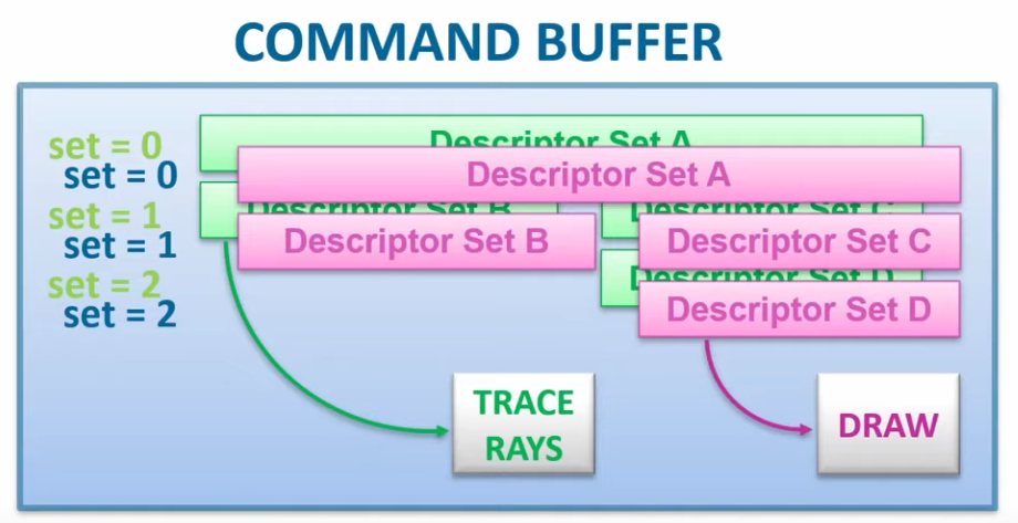 .
.
-
A raytracing command takes the currently bound descriptors from the raytracing bind point.
-
A draw command takes the currently bound descriptors from the graphics bind point.
-
The two don't interfere with each other.
-
-
-
layout-
Is a VkPipelineLayout object used to program the bindings.
-
-
firstSet-
Is the set number of the first descriptor set to be bound.
-
-
descriptorSetCount-
Is the number of elements in the
pDescriptorSetsarray.
-
-
pDescriptorSets-
Is a pointer to an array of handles to VkDescriptorSet objects describing the descriptor sets to bind to.
-
-
dynamicOffsetCount-
Is the number of dynamic offsets in the
pDynamicOffsetsarray.
-
-
pDynamicOffsets-
Is a pointer to an array of
uint32_tvalues specifying dynamic offsets.
-
-
Strategy: Descriptor Indexing (
EXT_descriptor_indexing
)
Plan
-
SSBOs and UBOs.
-
Can I just put different data without restriction?
-
Yes. See the SSBO section for that.
-
-
SSBOs or UBOs?
-
Using storage buffers exclusively instead of uniform buffers can increase GPU time on some architectures.
-
I'll use SSBO, as that was the general recommendation.
-
Maybe I'll mix both.
-
-
-
Material Data:
-
The Material index is used to look up material data from material storage buffer. The textures can then be accessed using the indices from the material data and the descriptor array.
-
Could be sent via push constants, but if I choose to go for indirect rendering (I should), then I cannot use push constants. I'd use the instance index (or similar) to index into a
[]Material_Data.
-
-
Model Matrix / Transforms:
-
Same as material data. I can send via push constants if direct drawing, or via
[]model_matrixif indirect drawing.
-
-
Globals:
-
Camera view/proj, lights, ambient, etc.
-
I could just bind this once as well.
-
-
Vertex:
-
Indirect vs Full bindless:
-
I'm not sure. I'll use Indirect Drawing for now. ChatGPU deep search didn't give me much.
-
-
Indirect Drawing:
-
For indirect drawing, it makes sense to just
vkCmdBindIndexBuffer, as I NEED the vertex shader to be called by the number of times I specified -
Plan: go for bindless first, drawing direct. instead of using the
instanceIDor similar, I just send the draw_data index via push constants. this way, the shader will be completely finalized, but then I batch the draws via draw indirect and use theinstanceIDinstead of the push constants ID -
Indirect Drawing will be the last thing
-
What not invert and do indirect first? I cannot do that, as the
instanceIDis useless without a bindless design! I NEED to have use for the ID, as I cannot bind desc sets or push constants for each individual draw! bindless first is a MUST.
-
-
Full bindless:
-
Using a large index buffer: We need to bind index data. If just like the vertex data, index data is allocated in one large index buffer, we only need to bind it once using
vkCmdBindIndexBuffer. -
While Vulkan provides a first-class way to specify vertex data by calling
vkCmdBindVertexBuffers, having to bind vertex buffers per-draw would not work for a fully bindless design.-
Additionally, some hardware doesn’t support vertex buffers as a first-class entity, and the driver has to emulate vertex buffer binding, which causes some CPU-side slowdowns when using
vkCmdBindVertexBuffers.
-
-
In a fully bindless design, we need to assume that all vertex buffers are suballocated in one large buffer and either use per-draw vertex offsets (
vertexOffsetargument tovkCmdDrawIndexed) to have hardware fetch data from it, or pass an offset in this buffer to the shader with each draw call and fetch data from the buffer in the shader. Both approaches can work well, and might be more or less efficient depending on the GPU.
-
-
Mesh Shaders.
-
Mesh Shaders is probably what is most true to the bindless strategy, but I won't go that way yet (too soon, too new).
-
-
Compute-
Maybe I could use a compute to do this for me, but then I'd lose the rasterizer.
-
-
-
Draw Data:
-
Indices to index into the other arrays.
struct DrawData { uint materialIndex; uint transformOffset; uint vertexOffset; uint unused0; // vec4 padding // ... extra gameplay data goes here };-
Vertex Shader:
DrawData dd = drawData[gl_DrawIDARB]; TransformData td = transformData[dd.transformOffset]; vec4 positionLocal = vec4(positionData[gl_VertexIndex + dd.vertexOffset], 1.0); vec3 positionWorld = mat4x3(td.transform[0], td.transform[1], td.transform[2]) * positionLocal; -
Frag Shader:
DrawData dd = drawData[drawId];
MaterialData md = materialData[dd.materialIndex];
vec4 albedo = texture(sampler2D(materialTextures[md.albedoTexture], albedoSampler), uv * vec2(md.tilingX, md.tilingY));
-
-
Slots:
-
tex buffer and material data buffer will be in the same set 0, or should they be 0/1?
-
Probably every bind is on desc set 0
-
The slots are based on frequency, but every single binding I'm talking about might just be bound once globally without problems
-
-
Overall:
-
[]textures -
[]material_data-
uv, flip, modulate, etc.
-
-
[]model_matrices-
transforms.
-
-
[]draw_data-
Indices to index into the other arrays.
-
-
vertex/indices
-
As input attributes, to then use Indirect Drawing.
-
-
About
-
Descriptor indexing is also known by the term "bindless", which refers to the fact that binding individual descriptor sets and descriptors is no longer the primary way we keep shader pipelines fed. Instead, we can bind a huge descriptor set once and just index into a large number of descriptors.
-
Adds a lot of flexibility to how resources are accessed.
-
"Bindless algorithms" are generally built around this flexibility where we either index freely into a lot of descriptors at once, or update descriptors where we please. In this model, "binding" descriptors is not a concern anymore.
-
The core functionality of this extension is that we can treat descriptor memory as one massive array, and we can freely access any resource we want at any time, by indexing.
-
If an array is large enough, an index into that array is indistinguishable from a pointer.
-
At most, we need to write/copy descriptors to where we need them and we can now consider descriptors more like memory blobs rather than highly structured API objects.
-
The introduction of descriptor indexing revealed that the descriptor model is all just smoke and mirrors. A descriptor is just a blob of binary data that the GPU can interpret in some meaningful way. The API calls to manage descriptors really just boils down to “copy magic bits here.”
-
Support :
-
Descriptor Indexing was created in 2018, so all hardware 2018+ should support it.
-
Core in Vulkan 1.2+
-
Limits queried using
VkPhysicalDeviceDescriptorIndexingPropertiesEXT. -
Features queried using
VkPhysicalDeviceDescriptorIndexingFeaturesEXT. -
Features toggled using
VkPhysicalDeviceDescriptorIndexingFeaturesEXT.
-
-
Required for :
-
Raytracing.
-
Many GPU Driven Rendering approaches.
-
-
Advantages :
-
No costly transfer of descriptor to GPU every frame. Shows up as spending a lot of time in
vkUpdateDescriptorSets(Vulkan) -
More flexible / dynamic rendering architecture
-
No manual tracking of per-object resource groups
-
Updating matrices and material data can be done in bulk before command recording
-
CPU and GPU refer to resources the same way, by index
-
GPU can store Texture IDs in a buffer for reference later in the frame – many uses
-
Easy Vertex Pulling – gets rid of binding vertex buffers
-
Write resource indexes from one shader into a buffer that another shader reads & uses
-
G-Buffer can use material ID instead of values
-
Terrain Splatmap contains material IDs allowing many materials to be used, instead of 4
-
And more…
-
-
Disadvantages :
-
Requires hardware support
-
May be too new for widespread use
-
Different “feature levels” can help ease transition
-
-
Different Performance Penalties
-
Arrays indexing can cause memory indirections
-
Fetching texture descriptors from an array indexed by material data indexed by material index can add an extra indirection on GPU compared to some alternative designs
-
-
-
“With great power comes great responsibility”
-
GPU can't verify that valid descriptors are bound
-
Validation is costlier: happens inside shaders
-
Can be difficult to debug
-
Descriptor management is up to the Application
-
-
On some hardware, various descriptor set limits may make this technique impractical to implement; to be able to index an arbitrary texture dynamically from the shader,
maxPerStageDescriptorSampledImagesshould be large enough to accomodate all material textures - while many desktop drivers expose a large limit here, the specification only guarantees a limit of 16, so bindless remains out of reach on some hardware that otherwise supports Vulkan.
-
-
Comparison: Indexing resources without the extension :
-
 .
.
-
Descriptor Indexing, explanation of "dynamic non-uniform" .
-
Good read.
-
-
Constant Indexing :
layout(set = 0, binding = 0) uniform sampler2D Tex[4]; texture(Tex[0], ...); texture(Tex[2], ...); // We can trivially flatten a constant-indexed array into individual resources, // so, constant indexing requires no fancy hardware indexing support. layout(set = 0, binding = 0) uniform sampler2D Tex0; layout(set = 0, binding = 1) uniform sampler2D Tex1; layout(set = 0, binding = 2) uniform sampler2D Tex2; layout(set = 0, binding = 3) uniform sampler2D Tex3; -
Image Array Dynamic Indexing :
-
The dynamic indexing features allow us to use a non-constant expression to index an array.
-
This has been supported since Vulkan 1.0.
-
-
The restriction is that the index must be dynamically uniform .
layout(set = 0, binding = 0) uniform sampler2D Tex[4]; texture(Tex[dynamically_uniform_expression], ...); -
-
Non-uniform vs Texture Atlas vs Texture Array :
-
Accessing arbitrary textures in a draw call is not a new problem, and graphics programmers have found ways over the years to workaround restrictions in older APIs. Rather than having multiple textures, it is technically possible to pack multiple textures into one texture resource, and sample from the correct part of the texture. This kind of technique is typically referred to as "texture atlas". Texture arrays (e.g. sampler2DArray) is another feature which can be used for similar purposes.
-
Problems with atlas:
-
Mip-mapping is hard to implement, and must likely be done manually with derivatives and math.
-
Anisotropic filtering is basically impossible.
-
Any other sampler addressing than
CLAMP_TO_EDGEis very awkward to implement. -
Cannot use different texture formats.
-
-
Problems with texture array:
-
All resolutions must match.
-
Number of array layers is limited (just 256 in min-spec).
-
Cannot use different texture formats.
-
-
Non-uniform indexing solves these issues since we can freely use multiple sampled image descriptors instead. Atlases and texture arrays still have their place. There are many use cases where these restrictions do not cause problems.
-
Non-uniform indexing is not just limited to textures (although that is the most relevant use case). Any descriptor type can be used as long as the device supports it.
-
-
Features
-
Update-after-bind :
-
In Vulkan, you generally have to create a
VkDescriptorSetand update it with all descriptors before you callvkCmdBindDescriptorSets. After a set is bound, the descriptor set cannot be updated again until the GPU is done using it. This gives drivers a lot of flexibility in how they access the descriptors. They are free to copy the descriptors and pack them somewhere else, promote them to hardware registers, the list goes on. -
Update-After-Bind gives flexibility to applications instead. Descriptors can be updated at any time as long as they are not actually accessed by the GPU. Descriptors can also be updated while the descriptor set is bound to a command buffer, which enables a "streaming" use case.
-
This means the application doesn’t have to unbind or re-record command buffers just to change descriptors—reducing CPU overhead in some streaming-resource scenarios.
-
-
Concurrent Updates :
-
Another "hidden" feature of update-after-bind is that it is possible to update the descriptor set from multiple threads. This is very useful for true "bindless" since unrelated tasks might want to update descriptors in different parts of the streamed/bindless descriptor set.
-
-
After and after :
-
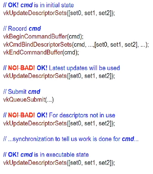 .
.
-
-
-
Non-uniform indexing :
-
While update-after-bind adds flexibility to descriptor management, non-uniform indexing adds great flexibility for shaders.
-
It completely removes all restrictions on how we index into arrays, but we must notify our intent to the compiler.
-
Normally, drivers and hardware can assume that the dynamically uniform guarantee holds, and optimize for that case.
-
If we use the
nonuniformEXTdecoration inGL_EXT_nonuniform_qualifierwe can let the compiler know that the guarantee does not necessarily hold, and the compiler will deal with it in the most efficient way possible for the target hardware. The rationale for having to annotate like this is that driver compiler backends would be forced to be more conservative than necessary if applications were not required to usenonuniformEXT. -
When to use it :
-
The invocation group :
-
The invocation group is a set of threads (invocations) which work together to perform a task.
-
In graphics pipelines, the invocation group is all threads which are spawned as part of a single draw command. This includes multiple instances, and for multi-draw-indirect it is limited to a single
gl_DrawID. -
In compute pipelines, the invocation group is a single workgroup, so it’s very easy to know when it is safe to avoid nonuniformEXT.
-
An expression is considered dynamically uniform if all invocations in an invocation group have the same value.
-
In other words, dynamically uniform means that the index is the same across all threads spawned by a draw command.
-
-
-
Interaction with Subgroups :
-
It is very easy to think that dynamically uniform just means "as long as the index is uniform in the subgroup, it’s fine!". This is certainly true for most (desktop) architectures, but not all.
-
It is technically possible that a value can be subgroup uniform, but still not dynamically uniform. Consider a case where we have a workgroup size of 128 threads, with a subgroup size of 32. Even if each subgroup does
subgroupBroadcastFirst()on the index, each subgroup might have different values, and thus, we still technically neednonuniformEXThere. If you know that you have only one subgroup per workgroup however,subgroupBroadcastFirst()is good enough. -
The safe thing to do is to just add
nonuniformEXTif you cannot prove the dynamically uniform property. If the compiler knows that it only really cares about subgroup uniformity, it could trivially optimize awaynonuniformEXT(subgroupBroadcastFirst())anyways. -
The common reason to use subgroups in the first place, is that it was an old workaround for lack of true non-uniform indexing, especially for desktop GPUs. A common pattern would be something like:
-
-
-
Implementation
-
Exemples :
-
odin_cool_engine:
-
odin_cool_engine/src/rp_ui.odin-
It just sends an index to the compute pipeline via push constants.
-
-
odin_cool_engine/src/renderer.odin:725-
It just sends an index to the compute pipeline via push constants.
-
-
-
-
Setup :
-
Check availability of the extension through
vk.EXT_DESCRIPTOR_INDEXING_EXTENSION_NAME+vk.EnumerateDeviceExtensionProperties. -
Check supported features of the extension through
vk.GetPhysicalDeviceFeatures2+vk.PhysicalDeviceDescriptorIndexingFeaturesas thepNextterm.
-
-
VkDescriptorSetLayoutCreateInfo.-
flags-
UPDATE_AFTER_BIND_POOL-
Specifies that descriptor sets using this layout must be allocated from a descriptor pool created with the
UPDATE_AFTER_BINDbit set. -
Descriptor set layouts created with this bit set have alternate limits for the maximum number of descriptors per-stage and per-pipeline layout.
-
The non-UpdateAfterBind limits only count descriptors in sets created without this flag. The UpdateAfterBind limits count all descriptors, but the limits may be higher than the non-UpdateAfterBind limits.
-
-
-
-
-
PARTIALLY_BOUND-
Specifies that descriptors in this binding that are not dynamically used, don't need to contain valid descriptors at the time the descriptors are consumed.
-
A descriptor is 'dynamically used' if any shader invocation executes an instruction that performs any memory access using the descriptor.
-
If a descriptor is not dynamically used, any resource referenced by the descriptor is not considered to be referenced during command execution.
-
-
This provides so it's not necessary to bind every descriptor. Allows a descriptor array binding to function even when not all array elements are written or valid.
-
This is critical if we want to make use of descriptor "streaming". A descriptor only has to be bound if it is actually used by a shader.
-
Without this feature, if you have an array of N descriptors and your shader indexes [0..N-1], all descriptors must be valid; otherwise behavior is undefined even if the shader never touches the uninitialized ones.
-
When enabled, you only need to write descriptors that the shader will index. “Holes” in the array are allowed, provided shader indices never touch them.
-
Use this when you want to leave “holes” in a large descriptor array (i.e. not update every element) without pre-filling unused slots with a fallback texture. When this flag is set, descriptors that are not dynamically used by the shader need not contain valid descriptors — but if the shader actually accesses an unwritten descriptor you still get undefined/invalid results. This is a convenience to avoid writing N fallback descriptors each time.
-
-
VARIABLE_DESCRIPTOR_COUNT-
Allows a descriptor binding to have a variable number of descriptors.
-
Use a variable amount of descriptors in an array.
-
Specifies that this is a variable-sized descriptor binding, whose size will be specified when a descriptor set is allocated using this layout.
-
This must only be used for the last binding in the descriptor set layout (i.e. the binding with the largest value of binding).
-
vk.DescriptorSetLayoutBinding.descriptorCount-
The value is treated as an upper bound on the size of the binding.
-
The actual count is supplied at allocation time via
VkDescriptorSetVariableDescriptorCountAllocateInfo. -
For the purposes of counting against limits such as
maxDescriptorSetandmaxPerStageDescriptor, the full value ofdescriptorCountis counted, except for descriptor bindings with a descriptor type ofDESCRIPTOR_TYPE_INLINE_UNIFORM_BLOCK, whenVkDescriptorSetLayoutCreateInfo.flagsdoes not containDESCRIPTOR_SET_LAYOUT_CREATE_DESCRIPTOR_BUFFER. In this case,descriptorCountspecifies the upper bound on the byte size of the binding; thus it counts against themaxInlineUniformBlockSizeandmaxInlineUniformTotalSizelimits instead.
-
-
When we later allocate the descriptor set, we can declare how large we want the array to be.
-
Be aware that there is a global limit to the number of descriptors can be allocated at any one time.
-
This is extremely useful when using
EXT_descriptor_indexing, since we do not have to allocate a fixed amount of descriptors for each descriptor set. -
In many cases, it is far more flexible to use runtime sized descriptor arrays.
-
Use this when you want the shader-visible length of a descriptor-array binding to be allocatable per-descriptor-set (i.e. different sets expose different array lengths) instead of using a single compile-time/ layout upper bound. At allocation you pass the actual count with VkDescriptorSetVariableDescriptorCountAllocateInfo. This reduces bookkeeping/pool usage and lets you avoid allocating the full upper bound for every set. Requires the descriptor-indexing feature be enabled and the variable-size binding must be the last binding in the set
-
-
UPDATE_AFTER_BIND-
Specifies that if descriptors in this binding are updated between when the descriptor set is bound in a command buffer and when that command buffer is submitted to a queue, then the submission will use the most recently set descriptors for this binding and the updates do not invalidate the command buffer. Descriptor bindings created with this flag are also partially exempt from the external synchronization requirement in
vkUpdateDescriptorSetWithTemplateKHRandvkUpdateDescriptorSets. Multiple descriptors with this flag set can be updated concurrently in different threads, though the same descriptor must not be updated concurrently by two threads. Descriptors with this flag set can be updated concurrently with the set being bound to a command buffer in another thread, but not concurrently with the set being reset or freed. -
Update-after-bind is another critical component of descriptor indexing, which allows us to update descriptors after a descriptor set has been bound to a command buffer.
-
This is critical for streaming descriptors, but it also relaxed threading requirements. Multiple threads can update descriptors concurrently on the same descriptor set.
-
UPDATE_AFTER_BINDdescriptors is somewhat of a precious resource, but min-spec in Vulkan is at least 500k descriptors, which should be more than enough.
-
-
UPDATE_UNUSED_WHILE_PENDING-
Specifies that descriptors in this binding can be updated after a command buffer has bound this descriptor set, or while a command buffer that uses this descriptor set is pending execution, as long as the descriptors that are updated are not used by those command buffers. Descriptor bindings created with this flag are also partially exempt from the external synchronization requirement in vkUpdateDescriptorSetWithTemplateKHR and vkUpdateDescriptorSets in the same way as for
UPDATE_AFTER_BIND. IfPARTIALLY_BOUNDis also set, then descriptors can be updated as long as they are not dynamically used by any shader invocations. IfPARTIALLY_BOUNDis not set, then descriptors can be updated as long as they are not statically used by any shader invocations. -
Update-Unused-While-Pending is somewhat subtle, and allows you to update a descriptor while a command buffer is executing.
-
The only restriction is that the descriptor cannot actually be accessed by the GPU.
-
-
UPDATE_AFTER_BINDvsUPDATE_UNUSED_WHILE_PENDING-
Both involve updates to descriptor sets after they are bound,
UPDATE_UNUSED_WHILE_PENDINGis a weaker requirement since it is only about descriptors that are not used, whereasUPDATE_AFTER_BINDrequires the implementation to observe updates to descriptors that are used.
-
-
-
Enabling Non-Uniform Indexing :
-
Enable
runtimeDescriptorArrayandshaderSampledImageArrayNonUniformIndexing(required for indexing an array ofCOMBINED_IMAGE_SAMPLER),descriptorBindingPartiallyBound(optional, to avoid undefined behavior on not fully populated arrays).-
If in Vulkan <1.2, then the features must be enabled in the
vk.PhysicalDeviceDescriptorIndexingFeatures. -
If in Vulkan >=1.2, then the features must be enabled in the
vk.PhysicalDeviceVulkan12Features.-
If this is not followed, you'll get:
[ERROR] --- vkCreateDevice(): pCreateInfo->pNext chain includes a VkPhysicalDeviceVulkan12Features structure, then it must not include a VkPhysicalDeviceDescriptorIndexingFeatures structure. The features in VkPhysicalDeviceDescriptorIndexingFeatures were promoted in Vulkan 1.2 and is also found in VkPhysicalDeviceVulkan12Features. To prevent one feature setting something to TRUE and the other to FALSE, only one struct containing the feature is allowed. pNext chain: VkDeviceCreateInfo::pNext -> [STRUCTURE_TYPE_LOADER_DEVICE_CREATE_INFO] -> [STRUCTURE_TYPE_LOADER_DEVICE_CREATE_INFO] -> [VkPhysicalDeviceVulkan13Features] -> [VkPhysicalDeviceVulkan12Features] -> [VkPhysicalDeviceDynamicRenderingUnusedAttachmentsFeaturesEXT] -> [VkPhysicalDeviceDescriptorIndexingFeatures]. The Vulkan spec states: If the pNext chain includes a VkPhysicalDeviceVulkan12Features structure, then it must not include a VkPhysicalDevice8BitStorageFeatures, VkPhysicalDeviceShaderAtomicInt64Features, VkPhysicalDeviceShaderFloat16Int8Features, VkPhysicalDeviceDescriptorIndexingFeatures, VkPhysicalDeviceScalarBlockLayoutFeatures, VkPhysicalDeviceImagelessFramebufferFeatures, VkPhysicalDeviceUniformBufferStandardLayoutFeatures, VkPhysicalDeviceShaderSubgroupExtendedTypesFeatures, VkPhysicalDeviceSeparateDepthStencilLayoutsFeatures, VkPhysicalDeviceHostQueryResetFeatures, VkPhysicalDeviceTimelineSemaphoreFeatures, VkPhysicalDeviceBufferDeviceAddressFeatures, or VkPhysicalDeviceVulkanMemoryModelFeatures structure (https://vulkan.lunarg.com/doc/view/1.4.328.0/windows/antora/spec/latest/chapters/devsandqueues.html#VUID-VkDeviceCreateInfo-pNext-02830) -
vulkan12_features := vk.PhysicalDeviceVulkan12Features{ // etc descriptorIndexing = true, // Descriptor Indexing: // Todo: Is this only for VK 1.2? runtimeDescriptorArray = true, // Descriptor Indexing: shaderSampledImageArrayNonUniformIndexing = true, // Descriptor Indexing: required for indexing an array of `COMBINED_IMAGE_SAMPLER`. descriptorBindingPartiallyBound = true, // Descriptor Indexing: optional, to avoid undefined behavior on not fully populated arrays. descriptorBindingVariableDescriptorCount = true, // Descriptor Indexing: Allows a descriptor binding to have a variable number of descriptors. // etc } -
-
In GLSL use the
GL_EXT_nonuniform_qualifierextension and wrap the index withnonuniformEXT(...)(or applynonuniformEXTto the loaded value) so the compiler emits the SPIR-VNonUniformEXTdecoration.
-
In the shader :
-
Constructors and builtin functions, which all have return types that are not qualified by
nonuniformEXT, will not generate nonuniform results.-
Shaders need to use the constructor syntax (or assignment to a
nonuniformEXT-qualified variable) to re-add thenonuniformEXTqualifier to the result of builtin functions. -
Correct:
-
It is important to note that to be 100% correct, we must use:
-
nonuniformEXT(sampler2D()). -
It is the final argument to a call like
texture()which determines if the access is to be considered non-uniform.
-
-
Wrong:
-
It is very common in the wild to see code like:
-
sampler2D(Textures[nonuniformEXT(in_texture_index)], ...) -
This looks very similar to HLSL, but it is somewhat wrong.
-
Generally, it will work on drivers, but it is not technically correct.
-
-
Examples:
-
sampler2D()is such a constructor, so we must addnonuniformEXTafterwards.-
out_frag_color = texture(nonuniformEXT(sampler2D(Textures[in_texture_index], ImmutableSampler)), in_uv);
-
-
-
-
Other use cases:
-
The nonuniform qualifier will propagate up to the final argument which is used in the load/store or atomic operation.
-
Examples:
// At the top
#extension GL_EXT_nonuniform_qualifier : require

uniform UBO { vec4 data; } UBOs[];
vec4 foo = UBOs[nonuniformEXT(index)].data;

buffer  SSBO { vec4 data; } SSBOs[];
vec4 foo = SSBOs[nonuniformEXT(index)].data;

uniform sampler2D Tex[];
vec4 foo = texture(Tex[nonuniformEXT(index)], uv);

uniform uimage2D Img[];
uint count = imageAtomicAdd(Img[nonuniformEXT(index)], uv, val);
#version 450 #extension GL_EXT_nonuniform_qualifier : require layout(local_size_x = 64) in; layout(set = 0, binding = 0) uniform sampler2D Combined[]; layout(set = 1, binding = 0) uniform texture2D Tex[]; layout(set = 2, binding = 0) uniform sampler Samp[]; layout(set = 3, binding = 0) uniform U { vec4 v; } UBO[]; layout(set = 4, binding = 0) buffer S { vec4 v; } SSBO[]; layout(set = 5, binding = 0, r32ui) uniform uimage2D Img[]; void main() { uint index = gl_GlobalInvocationID.x; vec2 uv = vec2(gl_GlobalInvocationID.yz) / 1024.0; vec4 a = textureLod(Combined[nonuniformEXT(index)], uv, 0.0); vec4 b = textureLod(nonuniformEXT(sampler2D(Tex[index], Samp[index])), uv, 0.0); vec4 c = UBO[nonuniformEXT(index)].v; vec4 d = SSBO[nonuniformEXT(index)].v; imageAtomicAdd(Img[nonuniformEXT(index)], ivec2(0), floatBitsToUint(a.x + b.y + c.z + d.w)); }
-
-
Caviats:
-
LOD:
-
Using implicit LOD with nonuniformEXT can be spicy! If the threads in a quad do not have the same index, LOD might not be computed correctly.
-
The
quadDivergentImplicitLODproperty lets you know if it will work. -
In this case however, it is completely fine, since the helper lanes in a quad must come from the same primitive, which all have the same flat fragment input.
-
-
-
Avoinding
nonuniformEXT:-
You might consider using subgroup operations to implement
nonuniformEXTon your own. -
This is technically out of spec, since the SPIR-V specification states that to avoid
nonuniformEXT, -
the shader must guarantee that the index is "dynamically uniform".
-
"Dynamically uniform" means the value is the same across all invocations in an "invocation group".
-
The invocation group is defined to be all invocations (threads) for:
-
An entire draw command (for graphics)
-
A single workgroup (for compute).
-
-
Avoiding
nonuniformEXTwith clever programming is far more likely to succeed when writing compute shaders, -
since the workgroup boundary serves as a much easier boundary to control than entire draw commands.
-
It is often possible to match workgroup to subgroup 1:1, unlike graphics where you cannot control how
-
quads are packed into subgroups at all.
-
The recommended approach here is to just let the compiler do its thing to avoid horrible bugs in the future.
-
-
-
-
Enabling Update-After-Bind :
-
In
VkDescriptorSetLayoutCreateInfowe must pass down binding flags in a separate struct withpNext.bindings_count := len(stage_set_layout.bindings) descriptor_bindings_flags := make([]vk.DescriptorBindingFlagsEXT, bindings_count, context.temp_allocator) for i in 0..<len(descriptor_bindings_flags) { descriptor_bindings_flags[i] = { .PARTIALLY_BOUND } } descriptor_bindings_flags[bindings_count - 1] += { .VARIABLE_DESCRIPTOR_COUNT } // Only the last binding supports VARIABLE_DESCRIPTOR_COUNT. descriptor_binding_flags_create_info := vk.DescriptorSetLayoutBindingFlagsCreateInfoEXT{ sType = .DESCRIPTOR_SET_LAYOUT_BINDING_FLAGS_CREATE_INFO_EXT, bindingCount = u32(bindings_count), pBindingFlags = raw_data(descriptor_bindings_flags), pNext = nil, } descriptor_set_layout_create_info := vk.DescriptorSetLayoutCreateInfo{ sType = .DESCRIPTOR_SET_LAYOUT_CREATE_INFO, flags = { }, bindingCount = u32(bindings_count), pBindings = raw_data(stage_set_layout.bindings), pNext = &descriptor_binding_flags_create_info, }// Num Descriptors static constexpr uint32_t NumDescriptorsStreaming = 2048; static constexpr uint32_t NumDescriptorsNonUniform = 64; // Pool uint32_t poolCount = NumDescriptorsStreaming + NumDescriptorsNonUniform; VkDescriptorPoolSize pool_size = vkb::initializers::descriptor_pool_size(DESCRIPTOR_TYPE_SAMPLED_IMAGE, poolCount); VkDescriptorPoolCreateInfo pool = vkb::initializers::descriptor_pool_create_info(1, &pool_size, 2); // Allocate VkDescriptorSetVariableDescriptorCountAllocateInfoEXT variable_info{}; allocate_info.pNext = &variable_info; variable_info.sType = STRUCTURE_TYPE_DESCRIPTOR_SET_VARIABLE_DESCRIPTOR_COUNT_ALLOCATE_INFO_EXT; variable_info.descriptorSetCount = 1; variable_info.pDescriptorCounts = &NumDescriptorsStreaming; CHECK(vkAllocateDescriptorSets(get_device().get_handle(), &allocate_info, &descriptors.descriptor_set_update_after_bind)); variable_info.pDescriptorCounts = &NumDescriptorsNonUniform; CHECK(vkAllocateDescriptorSets(get_device().get_handle(), &allocate_info, &descriptors.descriptor_set_nonuniform)); -
The
VkDescriptorPoolmust also be created withUPDATE_AFTER_BIND. Note that there is global limit to how many UPDATE_AFTER_BIND descriptors can be allocated at any point. The min-spec here is 500k, which should be good enough.
-
Strategy: Descriptor Buffers (
EXT_descriptor_buffer
)
-
Article .
-
Sample .
-
Released on (2022-11-21).
-
TLDR :
-
Descriptor sets are now backed by
VkBufferobjects where youmemcpyin descriptors. DeleteVkDescriptorPoolandVkDescriptorSetfrom the API, and have fun! -
Performance is either equal or better.
-
-
Coming from Descriptor Indexing, we use plain uints instead of actual descriptor sets, there are some design questions that come up.
-
Do we assign one uint per descriptor, or do we try to group them together such that we only need to push one base offset?
-
If we go with the latter, we might end up having to copy descriptors around. If we go with one uint per descriptor, we just added extra indirection on the GPU. GPU throughput might suffer with the added latency.
-
On the other hand, having to group descriptors linearly one after the other can easily lead to copy hell. Copying descriptors is still an abstracted operation that requires API calls to perform, and we cannot perform it on the GPU. The overhead of all these calls in the driver can be quite significant, especially in API layering. I’ve seen up to 10 million calls to “copy descriptor” per second which adds up.
-
Managing descriptors really starts looking more and more like just any other memory management problem. Let’s try translating existing API concepts into what they really are under the hood.
-
vkCreateDescriptorPool-
vkAllocateMemory. Memory type unknown, but likelyHOST_VISIBLEandDEVICE_LOCAL. Size of pool computed from pool entries.
-
-
vkAllocateDescriptorSets-
Linear or arena allocation from pool. Size and alignment computed from
VkDescriptorSetLayout.
-
-
vkUpdateDescriptorSets-
Writes raw descriptor data by copying payload from
VkImageView/VkSampler/VkBufferView. Write offset is deduced fromVkDescriptorSetLayoutand binding. TheVkDescriptorSetcontains a pointer toHOST_VISIBLEmapped CPU memory. Copies are similar.
-
-
vkCmdBindDescriptorSets-
Binds the GPU VA of the
VkDescriptorSetsomehow.
-
-
The descriptor buffer API effectively removes
VkDescriptorPoolandVkDescriptorSet. The APIs now expose lower level detail. -
For example, there’s now a bunch of properties to query:
typedef struct VkPhysicalDeviceDescriptorBufferPropertiesEXT {
    …
    size_t             samplerDescriptorSize;
    size_t             combinedImageSamplerDescriptorSize;
    size_t             sampledImageDescriptorSize;
    size_t             storageImageDescriptorSize;
    size_t             uniformTexelBufferDescriptorSize;
    size_t             robustUniformTexelBufferDescriptorSize;
    size_t             storageTexelBufferDescriptorSize;
    size_t             robustStorageTexelBufferDescriptorSize;
    size_t             uniformBufferDescriptorSize;
    size_t             robustUniformBufferDescriptorSize;
    size_t             storageBufferDescriptorSize;
    size_t             robustStorageBufferDescriptorSize;
    size_t             inputAttachmentDescriptorSize;
    size_t             accelerationStructureDescriptorSize;
    …
} VkPhysicalDeviceDescriptorBufferPropertiesEXT;
Strategy: Push Descriptor (
VK_KHR_push_descriptor
)
-
Promoted to core in Vulkan 1.4.
-
Last modified date: (2017-09-12).
-
This extension allows descriptors to be written into the command buffer, while the implementation is responsible for managing their memory. Push descriptors may enable easier porting from older APIs and in some cases can be more efficient than writing descriptors into descriptor sets.
-
Sample .
-
New Commands
-
vkCmdPushDescriptorSetKHR
-
-
If Vulkan Version 1.1 or
VK_KHR_descriptor_update_templateis supported:-
vkCmdPushDescriptorSetWithTemplateKHR
-
-
New Structures
-
Extending
VkPhysicalDeviceProperties2:-
VkPhysicalDevicePushDescriptorPropertiesKHR
-
-
-
New Enum Constants
-
VK_KHR_PUSH_DESCRIPTOR_EXTENSION_NAME -
VK_KHR_PUSH_DESCRIPTOR_SPEC_VERSION -
Extending
VkDescriptorSetLayoutCreateFlagBits:-
VK_DESCRIPTOR_SET_LAYOUT_CREATE_PUSH_DESCRIPTOR_BIT_KHR
-
-
Extending VkStructureType:
-
VK_STRUCTURE_TYPE_PHYSICAL_DEVICE_PUSH_DESCRIPTOR_PROPERTIES_KHR
-
-
-
If Vulkan Version 1.1 or VK_KHR_descriptor_update_template is supported:
-
Extending
VkDescriptorUpdateTemplateType:-
VK_DESCRIPTOR_UPDATE_TEMPLATE_TYPE_PUSH_DESCRIPTORS_KHR
-
-
Strategy: Bindful / Classic strategy (Slot-based / Frequency-based)
-
mna (midmidmid):
-
The reason you split up resources into multiple sets is actually to reduce the cost of
vkCmdBindDescriptorSets. The idea being that if you've got one set that holds scene-wide data and a different set that holds object-specific data, you only bind the scene stuff once and then just leave it bound. Then the per-object updates go faster because you're pushing much smaller descriptor sets into whatever special silicon descriptor sets map to on your particular GPU. Note: there are rules about how you have to arrange your sets (so like the scene-wide one has to be at a lower index than the per-object one), and all of the pipelines you use must have compatible layouts for the sets you aren't rebinding every time you switch to a different pipeline. Someone can correct me if I'm wrong, but if you switch to a pipeline that's got an incompatible layout for some descriptor set at index n then all descriptor sets at indices >= n need to be rebound. -
I think the only reason I'd change any of my stuff to bindless is if I hit however many hundreds of thousands of calls to
vkCmdBindDescriptorSetsit takes for descriptors to be a per-frame bottleneck. -
But I find descriptors pretty intuitive and easy to work with.
-
I didn't find them easy to work with when I first came to VK (from GL/D3D11-world), but now that I've got some scaffolding set up to manage them, they're easy sauce.
-
(They actually map pretty well to having worked with old console GPUs where you manage the command queue directly and have to think about resource bindings in terms of physical registers on the GPU. It was helpful to have that background.)
-
If you're working with descriptor sets, then you have lots of little objects whose lifetimes you need to track and manage. Getting them grouped into the appropriate set of pools cuts that number down to something that's not hard to manage. So, for me, I've got a dynamically allocated and recycled set of descriptor pools for stuff that changes every frame, and then I've got my materials grouped into pack files (for fast content loading) and each of those has one descriptor pool for all the sets for all of its materials. Easy peasy. For bindless, you need to figure out how you're going to divide up the big array of descriptors in your one mega set. There's different strategies for doing that. But you'll get a better description of them out of the bindless fans on the server.
-
Implementation-wise, I don't think there's a huge complexity difference between the two approaches. Bindless might be conceptually simpler since "it's just a big array" doesn't require as big of a mental shift as dividing resources up by usage and update frequency and thinking in those terms.
-
-
In the “classic” model, before you draw or dispatch, you must bind each resource to a specific descriptor binding or slot.
-
Example:
-
vkCmdBindDescriptorSets(...) -
Binding texture #0 for this draw, texture #1 for that draw, etc.
-
-
The shader uses a fixed binding index:
-
layout(set = 0, binding = 3) uniform sampler2D tex;
-
-
If you want to change which texture is used, you re-bind that descriptor.
-
 .
.
Specialization Constants
-
Allows a constant value in SPIR-V to be specified at
VkPipelinecreation time. -
This is powerful as it replaces the idea of doing preprocessor macros in the high level shading language (GLSL, HLSL, etc).
-
A way to provide constant values to a SPIR-V shader at pipeline creation time so the compiler can constant-fold, inline, and eliminate branches.
-
This yields code equivalent to having compiled separate shader variants with those constant values baked in.
-
-
This is not Vulkan exclusive, but an optimization from SPIR-V. OpenGL 4.6 can also use this feature.
-
Sample .
-
UBOs and Push Constants suffer from limited optimizations during shader compilation. Specialization Constants can provide those optimizations:
-
Uniform buffer objects (UBOs) are one of the most common approaches when it is necessary to set values within a shader at run-time and are used in many tutorials. UBOs are pushed to the shader just prior to its execution, this is after shader compilation which occurs during
vkCreateGraphicsPipelines. As these values are set after the shader has been compiled, the driver’s shader compiler has limited scope to perform optimizations to the shader during its compilation. This is because optimizations such as loop unrolling or unused code removal require the compiler to have knowledge of the values controlling them which is not possible with UBOs. Push constants also suffer from the same problems as UBOs, as they are also provided after the shader has been compiled. -
Specialization Constants are set before pipeline creation meaning these values are known during shader compilation, this allows the driver’s shader compiler to perform optimizations. In this optimisation process the compiler has the ability to remove unused code blocks and statically unroll which reduces the fragment cycles required by the shader which results in increased performance.
-
While specialization constants rely on knowing the required values before pipeline creation occurs, by trading off this flexibility and allowing the compiler to perform these optimizations you can increase the performance of your application easily and reduce shader code size.
-
-
Do :
-
Use compile-time specialization constants for all control flow. This allows compilation to completely remove unused code blocks and statically unroll loops.
-
-
Don’t :
-
Use control-flow which is parameterized by uniform values; specialize shaders for each control path needed instead.
-
-
Impact :
-
Reduced performance due to less efficient shader programs.
-
-
Example :
#version 450
layout (constant_id = 0) const float myColor = 1.0;
layout(location = 0) out vec4 outColor;

void main() {
    outColor = vec4(myColor);
}
struct myData { float myColor = 1.0f; } myData; VkSpecializationMapEntry mapEntry = {}; mapEntry.constantID = 0; // matches constant_id in GLSL and SpecId in SPIR-V mapEntry.offset = 0; mapEntry.size = sizeof(float); VkSpecializationInfo specializationInfo = {}; specializationInfo.mapEntryCount = 1; specializationInfo.pMapEntries = &mapEntry; specializationInfo.dataSize = sizeof(myData); specializationInfo.pData = &myData; VkGraphicsPipelineCreateInfo pipelineInfo = {}; pipelineInfo.pStages[fragIndex].pSpecializationInfo = &specializationInfo; // Create first pipeline with myColor as 1.0 vkCreateGraphicsPipelines(&pipelineInfo); // Create second pipeline with same shader, but sets different value myData.myColor = 0.5f; vkCreateGraphicsPipelines(&pipelineInfo); -
Use cases :
-
Toggling features:
-
Support for a feature in Vulkan isn’t known until runtime. This usage of specialization constants is to prevent writing two separate shaders, but instead embedding a constant runtime decision.
-
-
Improving backend optimizations:
-
Optimizing shader compilation from SPIR-V to GPU.
-
The “backend” here refers to the implementation’s compiler that takes the resulting SPIR-V and lowers it down to some ISA to run on the device.
-
Constant values allow a set of optimizations such as constant folding , dead code elimination , etc. to occur.
-
-
Affecting types and memory sizes:
-
It is possible to set the length of an array or a variable type used through a specialization constant.
-
It is important to notice that a compiler will need to allocate registers depending on these types and sizes. This means it is likely that a pipeline cache will fail if the difference is significant in registers allocated.
-
-
-
How they work :
-
The values are supplied using
VkSpecializationInfoattached to theVkPipelineShaderStageCreateInfo. -
In GLSL (or HLSL → SPIR-V) mark a constant with a constant id, e.g.
layout(constant_id = 0) const int MATERIAL_MODE = 0; -
Create
VkSpecializationMapEntryentries mappingconstantID→ offset/size in your data block. -
Fill a contiguous data buffer with the specialization values and set up
VkSpecializationInfo. -
Put the
VkSpecializationInfo*into the shader stageVkPipelineShaderStageCreateInfobefore callingvkCreateGraphicsPipelines. The backend finalizes (specializes/compiles) the shader at pipeline creation time.
-
-
How it affects the pipeline workflow :
-
TLDR :
-
It does not solve the pipeline workflow problem. It provides a system for shader optimization at SPIR-V→GPU compile time.
-
Specialization lets you get near-compile-time optimizations while still selecting variants at runtime, but it does not avoid having multiple created pipelines if you need multiple different specialized behaviors.
-
-
They do not, by themselves, precompile every possible branch permutation and keep them all resident for you. Each distinct set of specialization values that you want available at runtime normally corresponds to a separately created pipeline (the specialization values are applied during pipeline creation).
-
If you need multiple variants you must create (or reuse) the pipelines for those values.
-
If you have N independent boolean specialization choices, the number of possible specialized pipelines is 2^N (exponential growth). Creating many pipelines increases driver/state memory and creation time; use caching/derivatives/libraries if creation cost or count is a concern.
-
You cannot change a specialization constant per draw without binding a different pipeline: the specialization is fixed for the pipeline object, so per-draw changes require binding another pipeline or using a different strategy (uniforms, push constants, dynamic branching).
-
Different values mean different pipeline creation (driver work / memory).
-
"Is this a way to precompile every branching of a shader?"
-
Yes, but only if you actually create a pipeline for each variant.
-
Specialization constants let the driver compile-away branches at pipeline-creation time, but they do not magically produce all variants for you at draw time.
-
-
-
Recommendations :
-
Improving shader performance with vulkan's specialization constants .
-
When we create the Vulkan pipeline, we pass this specialization information using the
pSpecializationInfofield ofVkPipelineShaderStageCreateInfo. At that point, the driver will override the default value of the specialization constant with the value provided here before the shader code is optimized and native GPU code is generated, which allows the driver compiler backend to generate optimal code. -
It is possible to compile the same shader with different constant values in different pipelines, so even if a value changes often, so long as we have a finite number of combinations, we can generate optimized pipelines for each one ahead of the start of the rendering loop and just swap pipelines as needed while rendering.
-
"promote the UBO array to a push constant".
-
Applying specialization constants in a small number of shaders allowed me to benefit from loop unrolling and, most importantly, UBO promotion to push constants in the SSAO pass, obtaining performance improvements that ranged from 10% up to 20% depending on the configuration.
-
In other words:
-
The article shows how it's possible to pass a value to the shader during graphics pipeline creation so the shader is compiled from SPIR-V to GPU with that constant altered.
-
This helps by allowing the SPIR-V→GPU compiler to make optimization choices such as unrolling loops and removing branches; it can also enable UBO promotion.
-
The article does not suggest specialization constants solve the pipeline workflow problem. It focuses on compile-time shader optimizations.
-
-
-
Physical Storage Buffer (
KHR_buffer_device_address
)
-
Impressions :
-
(2025-09-08)
-
No descriptor sets.
-
Cool.
-
-
Very easy to set up.
-
Shader usage is a bit tricky; push constants are required to access buffers in many patterns.
-
More prone to programmer errors because there is no automatic bounds checking.
-
Hmm, idk, for now not sure.
-
-
Adds the ability to have “pointers in the shader”.
-
Buffer device address is a powerful and unique feature of Vulkan. It exposes GPU virtual addresses directly to the application, and the application can then use those addresses to access buffer data freely through pointers rather than descriptors.
-
This feature lets you place addresses in buffers and load and store to them inside shaders, with full capability to perform pointer arithmetic and other tricks.
-
Support :
-
Core in Vulkan 1.3.
-
Submitted at (2019-01-06), core at (2019-11-25).
-
Coverage :
-
(2025-09-08) 71.6%
-
79.8% Windows
-
70.9% Linux
-
68.7% Android
-
-
-
Lack of safety :
-
A critical thing to note is that a raw pointer has no idea of how much memory is safe to access. Unlike SSBOs when bounds-checking features are enabled, you must either do range checks yourself or avoid relying on out-of-bounds behavior.
-
-
Creating a buffer :
-
To be able to grab a device address from a
VkBuffer, you must create the buffer withSHADER_DEVICE_ADDRESSusage. -
The memory you bind that buffer to must be allocated with the corresponding flag via
pNext.
VkMemoryAllocateFlagsInfoKHR flags_info{STRUCTURE_TYPE_MEMORY_ALLOCATE_FLAGS_INFO_KHR}; flags_info.flags = MEMORY_ALLOCATE_DEVICE_ADDRESS_KHR; memory_allocation_info.pNext = &flags_info;-
After allocating and binding the buffer, query the address:
VkBufferDeviceAddressInfoKHR address_info{STRUCTURE_TYPE_BUFFER_DEVICE_ADDRESS_INFO_KHR}; address_info.buffer = buffer.buffer; buffer.gpu_address = vkGetBufferDeviceAddressKHR(device, &address_info);-
This address behaves like a normal address; you can offset the
VkDeviceAddressvalue as you see fit since it is auint64_t. -
There is no host-side alignment requirement enforced by the API for this value.
-
When using this pointer in shaders, you must provide and respect alignment semantics yourself, because the shader compiler cannot infer anything about a raw pointer loaded from memory.
-
You can place this pointer inside another buffer and use it as an indirection.
-
-
GL_EXT_buffer_reference:-
In Vulkan GLSL, the
GL_EXT_buffer_referenceextension allows declaring buffer blocks as pointer-like types rather than SSBOs. GLSL lacks true pointer types, so this extension exposes pointer-like behavior.
#extension GL_EXT_buffer_reference : require-
You can forward-declare types. Useful for linked lists and similar structures.
layout(buffer_reference) buffer Position;-
You can declare a buffer reference type. This is not an SSBO declaration, but effectively a pointer-to-struct.
layout(std430, buffer_reference, buffer_reference_align = 8) writeonly buffer Position { vec2 positions[]; };-
buffer_referencetags the type accordingly.buffer_reference_alignmarks the minimum alignment for pointers of this type. -
You can place the
Positiontype inside another buffer or another buffer reference type:
layout(std430, buffer_reference, buffer_reference_align = 8) readonly buffer PositionReferences { Position buffers[]; };-
Now you have an array of pointers.
-
You can also place a buffer reference inside push constants, an SSBO, or a UBO.
layout(std430, set = 0, binding = 0) readonly buffer Pointers { Positions positions[]; }; layout(std430, push_constant) uniform Registers { PositionReferences references; } registers; -
-
Casting pointers :
-
A key aspect of buffer device address is that we gain the capability to cast pointers freely.
-
While it is technically possible (and useful in some cases!) to "cast pointers" with SSBOs with clever use of aliased declarations like so:
layout(set = 0, binding = 0) buffer SSBO { float v1[]; }; layout(set = 0, binding = 0) buffer SSBO2 { vec4 v4[]; };-
It gets kind of hairy quickly, and not as flexible when dealing with composite types.
-
When we have casts between integers and pointers, we get the full madness that is pointer arithmetic. Nothing stops us from doing:
#extension GL_EXT_buffer_reference : require layout(buffer_reference) buffer PointerToFloat { float v; }; PointerToFloat pointer = load_pointer(); uint64_t int_pointer = uint64_t(pointer); int_pointer += offset; pointer = PointerToFloat(int_pointer); pointer.v = 42.0;-
Not all GPUs support 64-bit integers, so it is also possible to use
uvec2to represent pointers. This way, we can do raw pointer arithmetic in 32-bit, which might be more optimal anyways.
#extension GL_EXT_buffer_reference_uvec2 : require layout(buffer_reference) buffer PointerToFloat { float v; }; PointerToFloat pointer = load_pointer(); uvec2 int_pointer = uvec2(pointer); uint carry; uint lo = uaddCarry(int_pointer.x, offset, carry); uint hi = int_pointer.y + carry; pointer = PointerToFloat(uvec2(lo, hi)); pointer.v = 42.0; -
-
Debugging :
-
When debugging or capturing an application that uses buffer device addresses, there are some special driver requirements that are not universally supported. Essentially, to be able to capture application buffers which contain raw pointers, we must ensure that the device address for a given buffer remains stable when the capture is replayed in a new process. Applications do not have to do anything here, since tools like RenderDoc will enable the
bufferDeviceAddressCaptureReplayfeature for you, and deal with all the magic associated with address capture behind the scenes. If thebufferDeviceAddressCaptureReplayis not present however, tools like RenderDoc will mask out thebufferDeviceAddressfeature, so beware.
-
-
Sample .
-
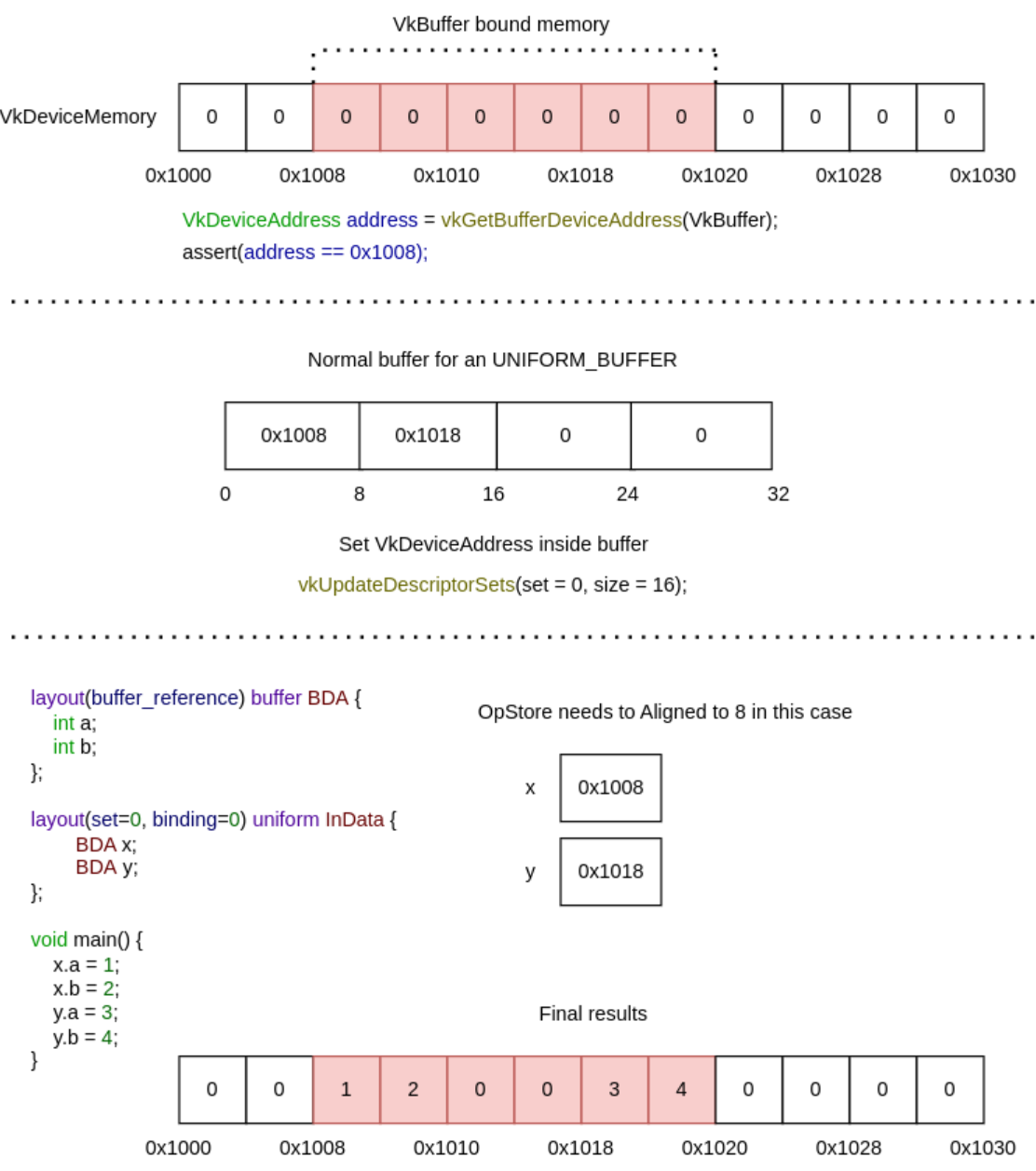 .
.
Memory Allocation
Info
-
-
Talk by AMD.
-
Shows no code.
-
The video is useful.
-
Memory Heaps, Memory Types.
-
Memory Blocks.
-
Suballocations.
-
Dos and Don'ts.
-
VMA.
-
VmaDumpVis.py to visualize the json file dumped by VMA.
-
-
-
Sounds more technical; I only saw parts of the talk.
-
Talk by AMD.
-
Shows code.
-
Memory Heaps, Memory Types.
-
Dos and Don'ts.
-
VMA.
-
-
There is additional level of indirection:
VkDeviceMemoryis allocated separately from creatingVkBuffer/VkImageand they must be bound together. -
Driver must be queried for supported memory heaps and memory types. Different GPU vendors provide different types of it.
-
It is recommended to allocate bigger chunks of memory and assign parts of them to particular resources, as there is a limit on maximum number of memory blocks that can be allocated.
-
When memory is over-committed on Windows, the OS memory manager may move allocations from video memory to system memory, the OS also may temporarily suspend a process from the GPU runlist in order to page out its allocations to make room for a different process’ allocations. There is no OS memory manager on Linux that mitigates over-commitment by automatically performing paging operations on memory objects.
-
Use
EXT_pageable_device_local_memoryto avoid demotion of critical resources by assigning memory priority. It’s also a good idea to set low priority to non-critical resources such as vertex and index buffers; the app can verify the performance impact by placing the resources in system memory. -
Use
EXT_pageable_device_local_memoryto also disable automatic promotion of allocations from system memory to video memory. -
Use dedicated memory allocations (
KHR_dedicated_allocation, core in VK 1.1) when appropriate. -
Using dedicated memory may improve performance for color and depth attachments, especially on pre-Turing GPUs.
-
Use
KHR_get_memory_requirements2(core in VK 1.1) to check whether an image/buffer requires dedicated allocation. -
Use host visible video memory to write data directly to video memory from the CPU. Such heap can be detected using
DEVICE_LOCAL | HOST_VISIBLE. Take into account that CPU writes to such memory may be slower compared to normal memory. CPU reads are significantly slower. Check BAR1 traffic using Nsight Systems for possible issues. -
Explicitly look for the
MEMORY_PROPERTY_DEVICE_LOCALwhen picking a memory type for resources, which should be stored in video memory. -
Don’t assume fixed heap configuration, always query and use the memory properties using
vkGetPhysicalDeviceMemoryProperties(). -
Don’t assume memory requirements of an image/buffer, use
vkGet*MemoryRequirements(). -
Don’t put every resource into a Dedicated Allocation.
-
For memory objects that are intended to be in device-local, do not just pick the first memory type. Pick one that is actually device-local.
-
The benefit is that we avoid CPU memory costs for lots of tiny buffers, as well as cache misses by using just the same buffer object and varying the offset.
-
This optimization applies to all buffers, but in the previous blog post on shader resource binding it was mentioned that the offsets are particularly good for uniform buffers.
-
Software developers use custom memory management for various reasons:
-
Making allocations often involves the operating system which is rather costly.
-
It is usually faster to re-use existing allocations rather than to free and reallocate new ones.
-
Objects that live in a continuous chunk of memory can enjoy better cache utilization.
-
Data that is aligned well for the hardware can be processed faster.
-
-
Memory is a precious resource, and it can involve several indirect costs by the operating systems. For example some operating systems have a linear cost over the number of allocations for each submission to a Vulkan Queue. Another scenario is that the operating system also handles the paging state of allocations depending on other proceses, we therefore encourage not using too many allocations and organizing them “wisely”.
-
Device Memory: This memory is used for buffers and images and the developer is responsible for their content.
-
Resource Pools: Objects such as CommandBuffers and DescriptorSets are allocated from pools, the actual content is indirectly written by the driver.
-
Custom Host Allocators: Depending on your control-freak level you may also want to provide your own host allocator that the driver can use for the api objects.
-
Heap: Depending on the hardware and platform, the device will expose a fixed number of heaps, from which you can allocate certain amount of memory in total. Discrete GPUs with dedicated memory will be different to mobile or integrated solutions that share memory with the CPU. Heaps support different memory types which must be queried from the device.
-
Memory type: When creating a resource such as a buffer, Vulkan will provide information about which memory types are compatible with the resource. Depending on additional usage flags, the developer must pick the right type, and based on the type, the appropriate heap.
-
Memory property flags: These flags encode caching behavior and whether we can map the memory to the host (CPU), or if the GPU has fast access to the memory.
-
Memory: This object represents an allocation from a certain heap with a user-defined size.
-
Resource (Buffer/Image): After querying for the memory requirements and picking a compatible allocation, the memory is associated with the resource at a certain offset. This offset must fulfill the provided alignment requirements. After this we can start using our resource for actual work.
-
Sub-Resource (Offsets/View): It is not required to use a resource only in its full extent, just like in OpenGL we can bind ranges (e.g. varying the starting offset of a vertex-buffer) or make use of views (e.g. individual slice and mipmap of a texture array).
-
The fact that we can manually bind resources to actual memory addresses, gives rise to the following points:
-
Resources may alias (share) the same region of memory.
-
Alignment requirements for offsets into an allocation must be manually managed.
-
-
Store multiple buffers, like the vertex and index buffer, into a single
VkBufferand use offsets in commands likevkCmdBindVertexBuffers. -
The advantage is that your data is more cache friendly in that case, because it’s closer together. It is even possible to reuse the same chunk of memory for multiple resources if they are not used during the same render operations, provided that their data is refreshed, of course.
-
This is known as aliasing and some Vulkan functions have explicit flags to specify that you want to do this.
-
Uniform Buffer Binding: As part of a DescriptorSet this would be the equivalent of an arbitrary glBindBufferRange(GL_UNIFORM_BUFFER, dset.binding, dset.bufferOffset, dset.bufferSize) in OpenGL. All information for the actual binding by the CommandBuffer is stored within the DescriptorSet itself.
-
Uniform Buffer Dynamic Binding: Similar as above, but with the ability to provide the bufferOffset later when recording the CommandBuffer, a bit like this pseudo code: CommandBuffer->BindDescriptorSet(setNumber, descriptorSet, &offset). It is very practical to use when sub-allocating uniform buffers from a larger buffer allocation.
-
Push Constants: PushConstants are uniform values that are stored within the CommandBuffer and can be accessed from the shaders similar to a single global uniform buffer. They provide enough bytes to hold some matrices or index values and the interpretation of the raw data is up the shader. You may recall glProgramEnvParameter from OpenGL providing something similar. The values are recorded with the CommandBuffer and cannot be altered afterwards: CommandBuffer->PushConstant(offset, size, &data)
-
Dynamic offsets are very fast for NVIDIA hardware. Re-using the same DescriptorSet with just different offsets is rather CPU-cache friendly as well compared to using and managing many DescriptorSets. NVIDIA’s OpenGL driver actually also optimizes uniform buffer binds where just the range changes for a binding unit.
Sub-allocation
-
In a real world application, you’re not supposed to actually call
vkAllocateMemoryfor every individual buffer. -
The maximum number of simultaneous memory allocations is limited by the
maxMemoryAllocationCountphysical device limit, which may be as low as4096even on high end hardware like an NVIDIA GTX 1080. -
The right way to allocate memory for a large number of objects at the same time is to create a custom allocator that splits up a single allocation among many different objects by using the
offsetparameters that we’ve seen in many functions. -
You can either implement such an allocator yourself, or use the VMA library provided by the GPUOpen initiative.
-
Sub-allocation is a first-class approach when working in Vulkan.
-
Memory is allocated in pages with a fixed size; sub-allocation reduces the number of OS-level allocations.
-
You should use memory sub-allocation.
-
Memory allocation and deallocation at OS/driver level is expensive.
-
vkAllocateMemory()is costly on the CPU. -
Cost can be reduced by suballocating from a large memory object.
-
Also note the
maxMemoryAllocationCountlimit which constrains the number of simultaneous allocations an application can have. -
A Vulkan app should aim to create large allocations and then manage them itself.
-
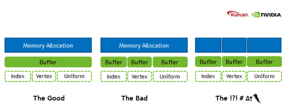
Arenas
Discussion around the availability of arenas in Vulkan
-
(2025-12-07)
-
Caio:
-
hello, is it possible to create a memory arena, placing all new objects in this region, and then freeing all this region without having to call the vkDestroyX functions? I'm having the impression that Vulkan memory management is rooted in RAII, which I don't like. All my games are managed through arenas, which I think is perfect, but for Vulkan I'm having to track each individual allocation and free each one at a time. I'm already treating memory as a big arena, but I'm having the overhead of calling the destruction of each resource separately.
-
-
CharlesG:
-
You don’t own the memory that backs vulkan objects. For command buffers and descriptors there are pools so the driver can do a good job with the backing memory scheme.
-
For VkDeviceMemory, you decide how to sub allocate them
-
-
Caio:
-
do I need to call destroy for objects like vkPipeline, VkPipelineLayout, VkDescriptorSetLayout, VkShaderModule, VkRenderPass, etc? I have lots of objects that should die exacly at the same time, but I'm having to free them one by one. I heard about suballocations for buffers and images, but what about these types of objects I mentioned?
-
-
VkIpotrick:
-
they require actualy cleanup, they are not just some memory
-
they might be referenced within other internal structures of the driver and have to be removed from those for example
-
-
CharlesG:
-
anything that you vkCreate must be vkDestroyed; Except command buffers and descriptors where it is sufficient to just destroy the pools.
-
Using Vulkan is a lot like networking with a remote server, lots of driver internals have implementation requirements that make arenas not the “obvious choice” (otherwise we’d see more of them)
-
-
Caio:
-
Is there a future in Vulkan where the decision of how to free the memory is not bound to the driver, but for the programmer? You mentioned how this is limited by what the driver allows, but could this change in the future and move towards being more low-level?
-
-
VkIpotrick:
-
no. i dont think that is feasable.
-
that would handcuff drivers so bad that you would be too low level. At that point a propper spec could be impossibly hard to create and maintain between vendors
-
vulkan drivers still have to do a loooot of things internally. its still highish level api
-
-
CharlesG:
-
I concur.
-
I want to reiterate that drivers deal with much more than host memory allocations, but device memory, external memory (to the process), OS api’s, display hardware, shader compilers. Some objects don’t actually DO anything on deletion (sampler come to mind because the handle stores the entire state for some implementations, when the private data ext isnt active)
-
Drivers get to ask the os on your behalf to map device memory into the host address space. And deal with you forgetting to unmap it during shutdown (though the OS is more likely to also clean up after user lode drivers…)
-
I mention that some objects are “free” to leak cause they didn’t allocate anything internally because that is an implementation detail that isnt possible on all hardware, so the API cant guarantee “free” sampler cleanup without screwing over some hardware. And it just ties their hands when it is no longer possible to put all the state into the handle any more in the future with extensions to the API
-
-
Caio:
-
well, I imagine this was the case, but still, I was hopeful there was some alternative for bulk deletion. Currently I just wrapped around the concept of shared lifetimes and created a pseudo-arena, which internally frees all the memory for me by calling each respective destructor. Still, it annoys me a bit knowing the design could be faster if I could bulk delete the content instead of being bound by what the driver exposes
-
I understand why it's not possible due to the current design by drivers, but I wish it were
-
my concern now is not the performance per se, but more about the freedom of having the option of managing memory in a way that could logically be faster (logically, as freeing a memory region is quite obviously faster than having to manage the state of different objects before deleting each of them individually). I'm not currently bound by the deletion times of those calls. I'm speaking more from a philosophical standpoint.
-
-
CharlesG:
-
Inb4 going all in on bindless and gpu driven where there just arent as many vulkan objects to manage
-
Fences and semaphores come to mind as prime examples of not just memory
-
-
Caio:
-
I'm trying to move it that way after trying bindful for a while, it's being much nicer and aligns with the vision I have of how memory is better managed;
-
-
CharlesG:
-
Suggestions for the API can be made in the vulkan-pain-points channel (although itd be good to link to this convo) and an issue can be made in the Vulkan-Docs github repo as thats the home of the specification. That said, this ask is not easily actionable so hard to quantify what “success” means.
-
All good, and going towards bindless is definitely going to suite your tastes better!
-
-
VkIpotrick:
-
bindless is simply better at this point
-
descriptor sets, layouts, pools etc made sense for old hardware, but now they are just very clunky oddly behaving abstractions
-
also with bindless you can have one static allocation for all descriptors
-
the ultimate memory management is static lifetime after all.
-
Alternatives and half-solutions
-
You cannot safely get the behavior you want — i.e. allocate many Vulkan resources and then legally free one big memory region while leaving the Vulkan object handles alive and never calling their destruction; on a conformant Vulkan implementation. Freeing VkDeviceMemory that backs resources while those resources are still live or still in use is undefined behavior / validation errors unless you guarantee the resources are never used again and the driver allows that. The Vulkan spec requires you to manage object lifetimes; drivers may have internal bookkeeping tied to those object handles that won’t be cleaned just by freeing the raw memory.
-
That said, you can achieve the practical “free everything by freeing a small number of objects/regions” without peppering vkDestroy* calls everywhere by changing how you structure resources. options that actually give you region-like semantics:
-
Mega-backings (buffers)
-
Never creating one Vulkan resource handle per logical allocation. In practice that means: create a small number of real Vulkan resources (big backing buffers / big images or sparse resources), suballocate from them, and operate using offsets/array-layer indices. When the region should die you destroy the backing objects (a few destroys) and free their VkDeviceMemory. No per-suballocation vkDestroy* calls are necessary because there are no per-suballocation Vulkan handles to destroy.
-
Create a small set of large backing VkDeviceMemory + VkBuffer objects (one per memory type/usage class you need).
-
Suballocate ranges from those big buffers and use offsets everywhere:
-
For vertex/index bindings: vkCmdBindVertexBuffers(..., firstBinding, 1, &bigBuffer, &offset).
-
For descriptors: VkDescriptorBufferInfo{ bigBuffer, offset, range } — descriptors can point at a buffer + offset without creating new VkBuffer handles.
-
When you’re done, you only need to vkDestroyBuffer / vkFreeMemory for a few big buffers, not for every tiny allocation.
-
Constraints: alignment, memoryRequirements and usage flags must be compatible for all suballocations placed in a given big buffer. If two allocations need different usage flags or memory types, they must go into different backing buffers.
-
-
Texture atlases / arrays (images)
-
Replace many small VkImage objects with a single large image (or texture array/array layers / atlas) and pack multiple textures into it. Use UV/array-layer indices in shader, or use VkImageView / descriptor indexing accordingly.
-
You then destroy and free one big image rather than many small ones. Tradeoffs: packing, mipmapping, filtering artifacts, and sampler/view creation.
-
Host Memory
Allocator (
VkAllocationCallbacks
)
-
VkAllocationCallbacksonly control host (CPU) allocations the loader/driver makes for Vulkan bookkeeping and temporary object. -
They do not give you a direct view or control of device (GPU) memory payloads.
-
Passing a non-NULL
pAllocatorto avkCreateXfunction causes the driver to call your callbacks for those host allocations. They do not switch the driver from using device heaps to host malloc; they only replace the host allocator functions used by the implementation. The allocation scope rules determine whether the allocation is command-scoped or object-scoped. -
Passing a custom
VkAllocationCallbackstovkCreateBufferlets you intercept and control the host memory the driver uses to represent the buffer object — but it does not tell you how many bytes of GPU heap were (or will be) consumed by the buffer’s storage. For the latter you must intercept device allocations (see below). -
To track real GPU memory you must track
vkAllocateMemory/vkFreeMemory(and any driver-internal device allocations) and/or useVK_EXT_memory_report/VK_EXT_memory_budgetto observe what the driver actually commits. -
Examples :
-
vkCreateBuffer(...):-
This call creates a buffer object handle and the driver's host-side bookkeeping for that object (descriptor, small metadata).
-
Those host allocations are the things
pAllocatoronvkCreateBuffercontrols. -
The call does not allocate GPU payload memory for the buffer contents.
-
The buffer becomes usable on the device only after you allocate
VkDeviceMemoryand bind it (or the driver performs some implicit allocation in non-standard implementations). -
The implementation goes as:
-
vk.CreateBuffer-
Create buffer. Host Visible handle. CPU Memory.
vk_check(vk.CreateBuffer(_device.handle, &buffer_create_info, &arena.gpu_alloc, &buffer_handle)) -
-
vk.GetBufferMemoryRequirements-
Prepare allocation_info for VkDeviceMemory. Choose a memoryTypeIndex with the desired properties
-
allocationSize and memoryTypeIndex determine whether the allocation will be device-local, host-visible, coherent, etc.
-
This properties decide if the memory is mappable from the CPU.
-
This call doesn't allocate anything.
mem_requirements: vk.MemoryRequirements vk.GetBufferMemoryRequirements(_device.handle, buffer_handle, &mem_requirements) mem_allocation_info := vk.MemoryAllocateInfo{ sType = .MEMORY_ALLOCATE_INFO, allocationSize = mem_requirements.size, memoryTypeIndex = device_find_memory_type(mem_requirements.memoryTypeBits, properties), } -
-
vk.AllocateMemory-
This is the call that requests a
VkDeviceMemoryallocation from a particular memory type/heap. -
Memory type is
HOST_VISIBLE:-
The driver will allocate from the heap that provides host mappings (which is typically system RAM or a host-visible region).
-
Effect: device payload is created — the
VkDeviceMemoryobject represents committed device memory (counts against the heap’s budget). -
On discrete GPUs this is often a segment of system memory that is mapped by the driver, or on integrated GPUs it may be the same physical RAM but treated as both host- and device-accessible.
-
The
pAllocatoryou pass to vkAllocateMemory only affects host-side allocations the driver does while processing the call; it does not change whether the allocation consumes device heap bytes.
-
-
Memory type is
DEVICE_LOCAL:-
Driver allocates a VkDeviceMemory from the device-local heap (on discrete GPUs this is the GPU VRAM heap). That is the device payload and consumes heap budget. The allocation is not host-visible, so you cannot vkMapMemory this memory.
-
Note: on integrated GPUs device-local may still be mappable because physical memory is shared — but that depends entirely on memory type flags exposed by the driver.
-
-
Memory type is
HOST VISIBLE + DEVICE_LOCAL:-
The allocation is created in a heap that the driver marks both device-local and host-visible. Physically this can mean: shared system RAM (integrated GPU) or a special heap the driver exposes that is accessible by both CPU and GPU. The VkDeviceMemory is committed and counts against that heap’s budget.
-
You may be able to
vkMapMemorythis memory because it is host-visible. Performance characteristics vary: host-visible+device-local memory can be slower to CPU-access than pure host memory or slower to GPU-access than pure device-local VRAM. -
On PC discrete GPUs this commonly corresponds to the GPU memory that is accessible through the PCIe BAR (Resizible-BAR / ReBAR) or a special small window the driver exposes. Allocation behavior: vkAllocateMemory allocates from that BAR-exposed heap (it consumes VRAM or a BAR-mapped window of VRAM).
-
vk_check(vk.AllocateMemory(_device.handle, &mem_allocation_info, nil, &buffer_memory)) -
-
vk.BindBufferMemory-
Binds one with the other (memory aliasing). Doesn't allocate anything
-
Binds the previously allocated device memory to the buffer object. Binding itself normally does not allocate additional device heap bytes; it just associates that payload region with the buffer handle.
-
After bind the buffer is usable for CPU mapping (if host-visible) and/or device operations.
vk_check(vk.BindBufferMemory(_device.handle, buffer_handle, buffer_memory, 0)) -
-
-
-
vkCreateGraphicsPipelines(...)-
Pipeline creation can be expensive and opaque.
-
During pipeline creation the driver may:
-
allocate host-side structures for the pipeline object (controlled by
pAllocatorpassed tovkCreateGraphicsPipelines), -
compile/optimize shaders, build internal representations,
-
and may allocate internal device resources (driver-controlled device memory, shader/kernel upload, caches) that are not the same as application
VkDeviceMemoryallocations. The spec explicitly allows drivers to perform internal device allocations for things like pipelines; those allocations are not controlled byVkAllocationCallbacks. If you need to see them, useVK_EXT_device_memory_report.
-
-
-
Allocation, Reallocation, Free, Internal Alloc, Internal Free
-
pfnAllocationorpfnReallocationmay be called in the following situations:-
Allocations scoped to a
VkDeviceorVkInstancemay be allocated from any API command. -
Allocations scoped to a command may be allocated from any API command.
-
Allocations scoped to a
VkPipelineCachemay only be allocated from:-
vkCreatePipelineCache -
vkMergePipelineCachesfordstCache -
vkCreateGraphicsPipelinesforpipelineCache -
vkCreateComputePipelinesforpipelineCache
-
-
Allocations scoped to a
VkValidationCacheEXTmay only be allocated from:-
vkCreateValidationCacheEXT -
vkMergeValidationCachesEXTfordstCache -
vkCreateShaderModulefor validationCache inVkShaderModuleValidationCacheCreateInfoEXT
-
-
Allocations scoped to a
VkDescriptorPoolmay only be allocated from:-
any command that takes the pool as a direct argument
-
vkAllocateDescriptorSetsfor thedescriptorPoolmember of itspAllocateInfoparameter -
vkCreateDescriptorPool
-
-
Allocations scoped to a
VkCommandPoolmay only be allocated from:-
any command that takes the pool as a direct argument
-
vkCreateCommandPool -
vkAllocateCommandBuffersfor thecommandPoolmember of itspAllocateInfoparameter -
any
vkCmd*command whosecommandBufferwas allocated from thatVkCommandPool
-
-
Allocations scoped to any other object may only be allocated in that object’s
vkCreate*command.
-
-
pfnFree, orpfnReallocationwith zero size, may be called in the following situations:-
Allocations scoped to a
VkDeviceor VkInstance may be freed from any API command. -
Allocations scoped to a command must be freed by any API command which allocates such memory.
-
Allocations scoped to a
VkPipelineCachemay be freed fromvkDestroyPipelineCache. -
Allocations scoped to a
VkValidationCacheEXTmay be freed fromvkDestroyValidationCacheEXT. -
Allocations scoped to a
VkDescriptorPoolmay be freed from-
any command that takes the pool as a direct argument
-
-
Allocations scoped to a
VkCommandPoolmay be freed from:-
any command that takes the pool as a direct argument
-
vkResetCommandBufferwhosecommandBufferwas allocated from thatVkCommandPool
-
-
Allocations scoped to any other object may be freed in that object’s
vkDestroy*command. -
Any command that allocates host memory may also free host memory of the same scope.
-
-
pfnAllocation-
If
pfnAllocationis unable to allocate the requested memory, it must return NULL. -
If the allocation was successful, it must return a valid pointer to memory allocation containing at least
sizebytes, and with the pointer value being a multiple ofalignment.
-
-
`pfnReallocation``
-
If the reallocation was successful,
pfnReallocationmust return an allocation with enough space for size bytes, and the contents of the original allocation from bytes zero to min(original size, new size) - 1 must be preserved in the returned allocation. -
If size is larger than the old size, the contents of the additional space are undefined .
-
If satisfying these requirements involves creating a new allocation, then the old allocation should be freed.
-
If
pOriginalis NULL, thenpfnReallocationmust behave equivalently to a call toPFN_vkAllocationFunctionwith the same parameter values (withoutpOriginal). -
If
sizeis zero, thenpfnReallocationmust behave equivalently to a call toPFN_vkFreeFunctionwith the samepUserDataparameter value, andpMemoryequal topOriginal. -
If
pOriginalis non-NULL, the implementation must ensure thatalignmentis equal to thealignmentused to originally allocatepOriginal. -
If this function fails and
pOriginalis non-NULL the application must not free the old allocation.
-
-
pfnFree-
May be
NULL, which the callback must handle safely. -
If
pMemoryis non-NULL, it must be a pointer previously allocated bypfnAllocationorpfnReallocation. -
The application should free this memory.
-
-
pfnInternalAllocation-
Upon allocation of executable memory,
pfnInternalAllocationwill be called. -
This is a purely informational callback.
-
-
pfnInternalFree-
Upon freeing executable memory,
pfnInternalFreewill be called. -
This is a purely informational callback.
-
-
If either of
pfnInternalAllocationorpfnInternalFreeis not NULL, both must be valid callbacks
Creating the allocator
-
VkAllocationCallbacksare for host-side allocations the Vulkan loader/driver makes (CPU memory for driver bookkeeping, staging buffers, etc.). -
Using
malloc/free:-
Is common and acceptable for many apps — but you must meet Vulkan’s callback semantics (alignment, reallocation behavior, thread-safety) and consider performance.
-
This is a normal, valid approach. It satisfies most apps and is what many people do in practice.
-
Caviats :
-
Alignment:
-
Vulkan allocators must return memory suitably aligned for any type the driver might need. Use posix_memalign/aligned_alloc on POSIX, _aligned_malloc on Windows, or otherwise ensure alignment. The Vulkan spec expects allocation functions to behave like platform allocators.
-
-
Reallocation semantics:
-
pfnReallocationmust implement C-like realloc semantics (grow/shrink, preserve contents if requested). If your platform realloc does not support required alignment, implement reallocation by allocating new aligned memory, copying the old contents, freeing the old pointer.
-
-
Thread-safety & performance:
-
Drivers can call the callbacks from multiple threads. The system malloc is usually thread-safe but can have global locks and contention. For high-frequency allocation patterns, a custom pool or thread-local allocator can reduce contention and improve predictable performance.
-
-
Internal allocation tracking:
-
VkAllocationCallbacksprovidepUserDataso you can route allocations to a custom pool/context for tracking or to implement more efficient pooling per object type.
-
-
-
-
The GPU VkDeviceMemory allocations (the ones created with vkAllocateMemory) are a separate resource and must be managed with Vulkan APIs and counted against the appropriate memory heap
-
If you use malloc for
VkAllocationCallbacks, you are only providing host-allocator behavior for driver/loader-side allocations.
Scope
-
Each allocation has an allocation scope defining its lifetime and which object it is associated with. Possible values passed to the allocationScope parameter of the callback functions specified by
VkAllocationCallbacks, indicating the allocation scope, are: -
COMMAND-
Specifies that the allocation is scoped to the duration of the Vulkan command.
-
The most specific allocator available is used (
DEVICE, elseINSTANCE).
-
-
OBJECT-
Specifies that the allocation is scoped to the lifetime of the Vulkan object that is being created or used.
-
The most specific allocator available is used (
OBJECT, elseDEVICE, elseINSTANCE).
-
-
CACHE-
Specifies that the allocation is scoped to the lifetime of a
VkPipelineCacheorVkValidationCacheEXTobject. -
If an allocation is associated with a
VkValidationCacheEXTorVkPipelineCacheobject, the allocator will use theCACHEallocation scope. -
The most specific allocator available is used (
CACHE, elseDEVICE, elseINSTANCE).
-
-
DEVICE-
Specifies that the allocation is scoped to the lifetime of the Vulkan device.
-
If an allocation is scoped to the lifetime of a device, the allocator will use an allocation scope of
DEVICE. -
The most specific allocator available is used (
DEVICE, elseINSTANCE).
-
-
INSTANCE-
Specifies that the allocation is scoped to the lifetime of the Vulkan instance.
-
If the allocation is scoped to the lifetime of an instance and the instance has an allocator, its allocator will be used with an allocation scope of
INSTANCE. -
Otherwise an implementation will allocate memory through an alternative mechanism that is unspecified.
-
-
Most Vulkan commands operate on a single object, or there is a sole object that is being created or manipulated. When an allocation uses an allocation scope of
OBJECTorCACHE, the allocation is scoped to the object being created or manipulated. -
When an implementation requires host memory, it will make callbacks to the application using the most specific allocator and allocation scope available:
-
Pools :
-
Objects that are allocated from pools do not specify their own allocator. When an implementation requires host memory for such an object, that memory is sourced from the object’s parent pool’s allocator.
-
Device Memory
-
Device memory is memory that is visible to the device — for example the contents of the image or buffer objects, which can be natively used by the device.
-
A Vulkan device operates on data in device memory via memory objects that are represented in the API by a
VkDeviceMemoryhandle. -
VkDeviceMemory.-
Opaque handle to a device memory object.
-
Properties
-
Memory properties of a physical device describe the memory heaps and memory types available.
-
To query memory properties, call
vkGetPhysicalDeviceMemoryProperties. -
VkPhysicalDeviceMemoryProperties-
Describes a number of memory heaps as well as a number of memory types that can be used to access memory allocated in those heaps.
-
Each heap describes a memory resource of a particular size, and each memory type describes a set of memory properties (e.g. host cached vs. uncached) that can be used with a given memory heap. Allocations using a particular memory type will consume resources from the heap indicated by that memory type’s heap index. More than one memory type may share each heap, and the heaps and memory types provide a mechanism to advertise an accurate size of the physical memory resources while allowing the memory to be used with a variety of different properties.
-
At least one heap must include
MEMORY_HEAP_DEVICE_LOCALinVkMemoryHeap.flags -
memoryTypeCountis the number of valid elements in thememoryTypesarray. -
memoryTypesis an array ofMAX_MEMORY_TYPESVkMemoryTypestructures describing the memory types that can be used to access memory allocated from the heaps specified by memoryHeaps. -
memoryHeapCountis the number of valid elements in thememoryHeapsarray. -
memoryHeapsis an array ofMAX_MEMORY_HEAPSVkMemoryHeapstructures describing the memory heaps from which memory can be allocated.
-
Device Memory Allocation
-
Memory requirements :
-
vkGetBufferMemoryRequirements-
Returns the memory requirements for specified Vulkan object
-
device-
Is the logical device that owns the buffer.
-
-
buffer-
Is the buffer to query.
-
-
pMemoryRequirements-
Is a pointer to a
VkMemoryRequirementsstructure in which the memory requirements of the buffer object are returned.
-
-
-
VkMemoryRequirements-
size-
Is the size, in bytes, of the memory allocation required for the resource.
-
The size of the required memory in bytes may differ from
bufferInfo.size.
-
-
alignment-
The offset in bytes where the buffer begins in the allocated region of memory, depends on
bufferInfo.usageandbufferInfo.flags.
-
-
memoryTypeBits-
Bit field of the memory types that are suitable for the buffer.
-
Bit
iis set if and only if the memory typeiin theVkPhysicalDeviceMemoryPropertiesstructure for the physical device is supported for the resource.
-
-
-
vkGetPhysicalDeviceMemoryProperties-
Reports memory information for the specified physical device
-
We'll use it to find a memory type that is suitable for the buffer itself.
-
vkGetPhysicalDeviceMemoryProperties2behaves similarly to vkGetPhysicalDeviceMemoryProperties , with the ability to return extended information in apNextchain of output structures. -
memoryHeaps-
Are distinct memory resources like dedicated VRAM and swap space in RAM for when VRAM runs out.
-
The different types of memory exist within these heaps.
-
Right now we’ll only concern ourselves with the type of memory and not the heap it comes from, but you can imagine that this can affect performance.
-
-
memoryTypes-
Consists of
VkMemoryTypestructs that specify the heap and properties of each memory type. -
The properties define special features of the memory, like being able to map it so we can write to it from the CPU.
-
VkMemoryType-
Structure specifying memory type
-
heapIndex-
Describes which memory heap this memory type corresponds to, and must be less than
memoryHeapCountfrom the VkPhysicalDeviceMemoryProperties structure.
-
-
propertyFlags-
Is a bitmask of VkMemoryPropertyFlagBits of properties for this memory type.
-
-
The most optimal memory has the
MEMORY_PROPERTY_DEVICE_LOCALflag and is usually not accessible by the CPU on dedicated graphics cards.
-
-
-
-
-
typeFilter-
Specify the bit field of memory types that are suitable.
-
That means that we can find the index of a suitable memory type by simply iterating over them and checking if the corresponding bit is set to
1. -
However, we’re not just interested in a memory type that is suitable for the vertex buffer.
-
We also need to be able to write our vertex data to that memory.
-
-
We may have more than one desirable property, so we should check if the result of the bitwise AND is not just non-zero, but equal to the desired properties bit field. If there is a memory type suitable for the buffer that also has all the properties we need, then we return its index, otherwise we throw an exception.
-
-
-
Allocation :
-
VkMemoryAllocateInfo-
allocationSize-
Is the size of the allocation in bytes.
-
-
memoryTypeIndex-
Is an index identifying a memory type from the
memoryTypesarray of thevkGetPhysicalDeviceMemoryPropertiesstruct, as defined in the 'memory requirements'.
-
-
-
vkAllocateMemory.-
To allocate memory objects.
-
device-
Is the logical device that owns the memory.
-
-
pAllocateInfo-
Is a pointer to a
VkMemoryAllocateInfostructure describing parameters of the allocation. A successfully returned allocation must use the requested parameters — no substitution is permitted by the implementation.
-
-
pAllocator-
Controls host memory allocation.
-
-
pMemory-
Is a pointer to a
VkDeviceMemoryhandle in which information about the allocated memory is returned.
-
-
-
Allocations returned by
vkAllocateMemoryare guaranteed to meet any alignment requirement of the implementation. For example, if an implementation requires 128 byte alignment for images and 64 byte alignment for buffers, the device memory returned through this mechanism would be 128-byte aligned. This ensures that applications can correctly suballocate objects of different types (with potentially different alignment requirements) in the same memory object. -
When memory is allocated, its contents are undefined with the following constraint:
-
The contents of unprotected memory must not be a function of the contents of data protected memory objects, even if those memory objects were previously freed.
-
The contents of memory allocated by one application should not be a function of data from protected memory objects of another application, even if those memory objects were previously freed.
-
-
The maximum number of valid memory allocations that can exist simultaneously within a VkDevice may be restricted by implementation- or platform-dependent limits. The maxMemoryAllocationCount feature describes the number of allocations that can exist simultaneously before encountering these internal limits.
-
-
Freeing :
-
To free a memory object, call
vkFreeMemory. -
Before freeing a memory object, an application must ensure the memory object is no longer in use by the device — for example by command buffers in the pending state. Memory can be freed whilst still bound to resources, but those resources must not be used afterwards. Freeing a memory object releases the reference it held, if any, to its payload. If there are still any bound images or buffers, the memory object’s payload may not be immediately released by the implementation, but must be released by the time all bound images and buffers have been destroyed. Once all references to a payload are released, it is returned to the heap from which it was allocated.
-
How memory objects are bound to Images and Buffers is described in detail in the [Resource Memory Association] section.
-
If a memory object is mapped at the time it is freed, it is implicitly unmapped.
-
Host writes are not implicitly flushed when the memory object is unmapped, but the implementation must guarantee that writes that have not been flushed do not affect any other memory.
-
Resource Memory Association
-
Resources are initially created as virtual allocations with no backing memory. Device memory is allocated separately and then associated with the resource. This association is done differently for sparse and non-sparse resources.
-
Resources created with any of the sparse creation flags are considered sparse resources. Resources created without these flags are non-sparse. The details on resource memory association for sparse resources is described in Sparse Resources.
-
Non-sparse resources must be bound completely and contiguously to a single VkDeviceMemory object before the resource is passed as a parameter to any of the following operations:
-
creating buffer, image, or tensor views
-
updating descriptor sets
-
recording commands in a command buffer
-
-
Once bound, the memory binding is immutable for the lifetime of the resource.
-
In a logical device representing more than one physical device, buffer and image resources exist on all physical devices but can be bound to memory differently on each. Each such replicated resource is an instance of the resource. For sparse resources, each instance can be bound to memory arbitrarily differently. For non-sparse resources, each instance can either be bound to the local or a peer instance of the memory, or for images can be bound to rectangular regions from the local and/or peer instances. When a resource is used in a descriptor set, each physical device interprets the descriptor according to its own instance’s binding to memory.
-
Sparse resources let you create
VkBufferandVkImageobjects which are bound non-contiguously to one or moreVkDeviceMemoryallocations.
Host Access
-
Also check GPU .
-
Memory objects created with
vkAllocateMemoryare not directly host accessible. -
Memory objects created with the memory property
MEMORY_PROPERTY_HOST_VISIBLEare considered mappable. Memory objects must be mappable in order to be successfully mapped on the host. -
vkMapMemory-
This function allows us to access a region of the specified memory resource defined by an offset and size.
-
Used to retrieve a host virtual address pointer to a region of a mappable memory object.
-
It is also possible to specify the special value
WHOLE_SIZEto map all of the memory. -
device-
Is the logical device that owns the memory.
-
-
memory-
Is the
VkDeviceMemoryobject to be mapped.
-
-
offset-
Is a zero-based byte offset from the beginning of the memory object.
-
-
size-
Is the size of the memory range to map, or
WHOLE_SIZEto map from offset to the end of the allocation.
-
-
flags-
Is a bitmask of
VkMemoryMapFlagBitsspecifying additional parameters of the memory map operation.
-
-
ppData-
Is a pointer to a
void*variable in which a host-accessible pointer to the beginning of the mapped range is returned. The value of the returned pointer minus offset must be aligned toVkPhysicalDeviceLimits.minMemoryMapAlignment. -
Acts like regular RAM, but physically points to GPU memory.
-
-
-
After a successful call to
vkMapMemorythe memory object memory is considered to be currently host mapped. -
It is an application error to call vkMapMemory on a memory object that is already host mapped.
-
vkMapMemorydoes not check whether the device memory is currently in use before returning the host-accessible pointer. -
If the device memory was allocated without the
MEMORY_PROPERTY_HOST_COHERENTset, these guarantees must be made for an extended range: the application must round down the start of the range to the nearest multiple ofVkPhysicalDeviceLimits.nonCoherentAtomSize, and round the end of the range up to the nearest multiple ofVkPhysicalDeviceLimits.nonCoherentAtomSize. -
Problem :
-
The driver may not immediately copy the data into the buffer memory, for example, because of caching.
-
It is also possible that writes to the buffer are not visible in the mapped memory yet.
-
There are two ways to deal with that problem:
-
Use a memory heap that is host coherent, indicated with
MEMORY_PROPERTY_HOST_COHERENT -
Call
vkFlushMappedMemoryRangesafter writing to the mapped memory, and callvkInvalidateMappedMemoryRangesbefore reading from the mapped memory.
-
-
Flushing memory ranges or using a coherent memory heap means that the driver will be aware of our writings to the buffer, but it doesn’t mean that they are actually visible on the GPU yet. The transfer of data to the GPU is an operation that happens in the background, and the specification simply tells us that it is guaranteed to be complete as of the next call to
vkQueueSubmit.
-
-
Minimum Alignment :
-
-
minMemoryMapAlignment-
Is the minimum required alignment, in bytes, of host visible memory allocations within the host address space.
-
When mapping a memory allocation with vkMapMemory , subtracting
offsetbytes from the returned pointer will always produce an integer multiple of this limit. -
See https://registry.khronos.org/vulkan/specs/latest/html/vkspec.html#memory-device-hostaccess .
-
The value must be a power of two.
-
-
nonCoherentAtomSize-
Is the size and alignment in bytes that bounds concurrent access to host-mapped device memory .
-
The value must be a power of two.
-
-
-
ChatGPT:
-
Dynamic offsets:
-
If you used
DESCRIPTOR_TYPE_UNIFORM_BUFFER_DYNAMICorDESCRIPTOR_TYPE_STORAGE_BUFFER_DYNAMICin yourVkDescriptorSetLayoutBinding.-
That is the definition of a dynamic descriptor.
-
-
If you call
vkCmdBindDescriptorSets(..., dynamicOffsetCount, pDynamicOffsets). IfdynamicOffsetCount > 0andpDynamicOffsetsis non-null you are supplying dynamic offsets at bind time.
-
-
How offsets are applied:
-
Non-dynamic descriptor:
-
The
VkDescriptorBufferInfo.offsetyou gave tovkUpdateDescriptorSetsis baked into the descriptor. -
That
offsetmust be a multiple ofminUniformBufferOffsetAlignment.
-
-
Dynamic descriptor:
-
The descriptor stores a base
offset/range, and the runtime adds the dynamic offset(s) you pass tovkCmdBindDescriptorSets. -
Each dynamic offset must be a multiple of
minUniformBufferOffsetAlignment.
-
-
-
If you are not using Dynamic Offsets in the
vkCmdBindDescriptorSets, nor using offsets in theVkDescriptorBufferInfo, then you don't need to worry about this limit.
-
-
Staging buffer
-
Use a host visible buffer as temporary buffer and use a device local buffer as actual buffer.
-
The host visible buffer should have use
BUFFER_USAGE_TRANSFER_SRC, and the device local buffer should have useBUFFER_USAGE_TRANSFER_DST. -
The contents of the host visible buffer is copied to the device local buffer using
vkCmdCopyBuffer. -
 .
.
-
Buffer copy requirements :
-
Requires a queue family that supports transfer operations, which is indicated using
QUEUE_TRANSFER.-
Any queue family with
QUEUE_GRAPHICSorQUEUE_COMPUTEcapabilities already implicitly supportQUEUE_TRANSFERoperations. -
A different queue family specifically for transfer operations could be used.
-
It will require you to make the following modifications to your program:
-
Modify
QueueFamilyIndicesandfindQueueFamiliesto explicitly look for a queue family with theQUEUE_TRANSFERbit, but not theQUEUE_GRAPHICS. -
Modify
createLogicalDeviceto request a handle to the transfer queue -
Create a second command pool for command buffers that are submitted on the transfer queue family
-
Change the
sharingModeof resources to beSHARING_MODE_CONCURRENTand specify both the graphics and transfer queue families -
Submit any transfer commands like
vkCmdCopyBuffer(which we’ll be using in this chapter) to the transfer queue instead of the graphics queue
-
-
-
This will teach you a lot about how resources are shared between queue families.
-
Caio: Ok, but what's the benefits of using different queues? I don't know.
-
-
BAR (Base Address Register)
-
See GPU .
Memory Aliasing
-
A range of a VkDeviceMemory allocation is aliased if it is bound to multiple resources simultaneously, as described below, via
vkBindImageMemory,vkBindBufferMemory,vkBindAccelerationStructureMemoryNV,vkBindTensorMemoryARM, via sparse memory bindings, or by binding the memory to resources in multiple Vulkan instances or external APIs using external memory handle export and import mechanisms. -
Consider two resources, resourceA and resourceB, bound respectively to memory rangeA and rangeB. Let paddedRangeA and paddedRangeB be, respectively, rangeA and rangeB aligned to bufferImageGranularity. If the resources are both linear or both non-linear (as defined in the Glossary), then the resources alias the memory in the intersection of rangeA and rangeB. If one resource is linear and the other is non-linear, then the resources alias the memory in the intersection of paddedRangeA and paddedRangeB.
-
The implementation-dependent limit bufferImageGranularity also applies to tensor resources.
-
Memory aliasing can be useful to reduce the total device memory footprint of an application, if some large resources are used for disjoint periods of time.
-
vkBindBufferMemory().-
If memory allocation was successful, then we can now associate this memory with the buffer using this function.
-
offset-
Offset within the region of memory.
-
Since this memory is allocated specifically for this the vertex buffer, the offset is simply
0. -
If the offset is non-zero, then it is required to be divisible by
memRequirements.alignment.
-
-
Lazily Allocated Memory
-
If the memory object is allocated from a heap with the
MEMORY_PROPERTY_LAZILY_ALLOCATEDbit set, that object’s backing memory may be provided by the implementation lazily. The actual committed size of the memory may initially be as small as zero (or as large as the requested size), and monotonically increases as additional memory is needed. -
A memory type with this flag set is only allowed to be bound to a VkImage whose usage flags include
IMAGE_USAGE_TRANSIENT_ATTACHMENT.
Protected Memory
-
Protected memory divides device memory into protected device memory and unprotected device memory.
-
Unprotected Device Memory :
-
Unprotected device memory, which can be visible to the device and can be visible to the host
-
Unprotected images, unprotected tensors, and unprotected buffers, to which unprotected memory can be bound
-
Unprotected command buffers, which can be submitted to a device queue to execute unprotected queue operations
-
Unprotected device queues, to which unprotected command buffers can be submitted
-
Unprotected queue submissions, through which unprotected command buffers can be submitted
-
Unprotected queue operations
-
-
Protected Device Memory :
-
Protected device memory, which can be visible to the device but must not be visible to the host
-
Protected images, protected tensors, and protected buffers, to which protected memory can be bound
-
Protected command buffers, which can be submitted to a protected-capable device queue to execute protected queue operations
-
Protected-capable device queues, to which unprotected command buffers or protected command buffers can be submitted
-
Protected queue submissions, through which protected command buffers can be submitted
-
Protected queue operations
-
Tracking GPU Memory
-
Vulkan does not expose fixed per-object byte counts for most objects — exact memory use is implementation and driver-dependent. Some objects (
VkImage,VkBuffer) must be bound toVkDeviceMemoryyou allocate (so you can know their size). Many other objects (pipelines, command buffers, descriptor sets, semaphores, imageviews, pipeline layouts, etc.) often cause hidden driver allocations that may live in host memory, device memory, or both — and those allocations’ size and placement vary by driver and GPU.
By object
-
VkInstance/VkPhysicalDevice/VkDevice(handles):-
Small host-side allocations (process RAM). Measure via your VkAllocationCallbacks or by tracking driver host allocations. These are host-visible (they are just process memory)
-
-
VkImageView/VkBufferView/VkSampler:-
Lightweight, usually host memory (small driver structures). They rarely allocate large device memory; they may cause small host allocations. Implementation dependent but small (tens to a few hundred bytes each in many drivers).
-
-
VkDescriptorSetLayout/VkPipelineLayout/VkDescriptorSet(layout vs sets):-
Layout and pipeline layout are small host structures (host memory). Descriptor sets and descriptor pools may be implemented in host memory or device memory; larger descriptor usage (large arrays, inline uniform blocks, inline immutable samplers, or driver internal structures) can cause real device allocations. Behavior is driver dependent.
-
-
VkPipeline(graphics/compute):-
Creation can cause hidden device and/or host allocations (compiled device binaries, GPU resident state). The spec explicitly allows implementations to allocate device memory during pipeline creation; the pipeline cache and pipeline executable properties APIs can help quantify some of this. Pipeline objects range from a few KB to multiple MB depending on driver, the number/complexity of shaders, and whether the driver stores compiled GPU blobs. Use
VK_KHR_pipeline_executable_propertiesand pipeline cache queries to inspect pipeline internals.
-
-
VkPipelineCache:-
Contains data you can query with
vkGetPipelineCacheData— that returns host-visible data you can size and persist.
-
-
VkCommandPool/VkCommandBuffer:-
Command buffers are allocated from a pool; actual memory holding recorded commands is driver-managed and may be placed in device local memory (GPU command stream) or host memory, depending on driver and OS. Sizes vary widely and are not exposed directly; instrument via driver callbacks or
VK_EXT_device_memory_report.
-
-
VkSemaphore/VkFence:-
Binary semaphores and fences may use kernel/OS constructs or small host/device allocations; timeline semaphores hold a 64-bit value and may be backed by device memory on some implementations. Typically small (a few bytes to some KB) but driver dependent.
-
-
VkSwapchainKHRand presentable images:-
Swapchain images are VkImage objects with memory managed by the WSI/driver; they are typically DEVICE_LOCAL and can live in special presentable heaps. Their size equals image size × format bits × layers/levels plus padding (obtainable from
vkGetImageMemoryRequirementsfor images you allocate yourself; for WSI images use provided queries andVK_EXT_memory_budgetto monitor heap consumption).
-
-
Typical magnitude examples (illustrative only)
-
Instance / layouts / view objects: tens to hundreds of bytes each (host).
-
Small buffers (uniform buffers) / small images: KBs to MBs, depending on dimensions and format — these are the allocations you make explicitly.
-
Pipelines: KBs → multiple MBs (depends on shader complexity and driver caching). Use pipeline executable queries to get an estimate.
-
Command buffer pools / driver command memory: KBs → MBs per many command buffers; driver dependent.
-
These numbers must be measured on your target hardware — they are not constant across drivers.
-
Tracking
-
Centralize and wrap all
vkAllocateMemory/vkFreeMemorycalls.-
Record:
VkDeviceMemoryhandle,VkMemoryAllocateInfosize/flags, chosen memory type index, and optionally theVkDeviceSizeand offset for any suballocator logic. Suballocation (oneVkDeviceMemoryused for many buffers/images) means you must additionally record your suballocations. Use this table as the authoritative committed GPU bytes. (Spec:vkAllocateMemoryproduces the device memory payload.)
-
-
Track suballocation bookkeeping in your allocator.
-
If you allocate large
VkDeviceMemoryblocks and suballocate slices for many buffers/images, account the slices into your counters (otherwise counting onlyVkDeviceMemoryhandles will under- or over-count usage).
-
-
Hook creation / bind points to attribute usage.
-
When you
vkBindBufferMemory/vkBindImageMemory, attach which application object is consuming which suballocation — this lets you produce per-buffer/per-image committed usage.
-
-
Use
VK_EXT_memory_budgetfor driver-reported heap usage/budgets.-
Query
VkPhysicalDeviceMemoryBudgetPropertiesEXTviavkGetPhysicalDeviceMemoryProperties2to getheapBudgetandheapUsagevalues per heap. -
These are implementation-provided and reflect other processes and driver internal usage; use them as cross-checks and to warn when you approach limits.
-
Use it to see heap usage and budget per heap (useful to spot overall device local vs host mapped heap pressure). This is not per-object, but shows total heap usage and remaining budget. Combine with device_memory_report events to attribute heap changes to objects.
-
-
Enable
VK_EXT_device_memory_reportfor visibility into driver-internal allocations.-
This extension gives callbacks for driver-side device memory events (allocate/free/import) including allocations not exposed as VkDeviceMemory (for example, allocations made internally during pipeline creation). Use it for debugging and to catch allocations that your vkAllocateMemory wrapper would miss.
-
-
Account for dedicated allocations and imports.
-
You can use
VK_KHR_dedicated_allocationto force one allocation per resource. If you allocate oneVkDeviceMemoryper resource you know exactly how many bytes each resource consumes. -
If an allocation is made with
VkMemoryDedicatedAllocateInfoor via external memory import, count that device memory appropriately — it typically represents a whole allocation tied to a single image/buffer.
-
-
Use
VK_KHR_pipeline_executable_propertiesfor pipeline internals.-
Create the pipeline with the capture flag (
VK_PIPELINE_CREATE_CAPTURE_STATISTICS_BIT_KHR) and callvkGetPipelineExecutablePropertiesKHR/vkGetPipelineExecutableStatisticsKHRto obtain compile-time statistics and sizes for pipeline executables that the driver produced. This helps measure how much space pipeline compilation produced (but it may not show every byte the driver reserved at runtime).
-
-
Vendor tools + RenderDoc / NSight / Radeon GPU Profiler.
-
These tools often show GPU memory usage, allocations, and sometimes attribute memory to API objects. Use them to validate your in-process accounting.
-
Device Memory Report (
VK_EXT_device_memory_report
)
-
Last updated (2021-01-06).
-
Info .
-
Allows registration of device memory event callbacks upon device creation, so that applications or middleware can obtain detailed information about memory usage and how memory is associated with Vulkan objects. This extension exposes the actual underlying device memory usage, including allocations that are not normally visible to the application, such as memory consumed by
vkCreateGraphicsPipelines. It is intended primarily for use by debug tooling rather than for production applications.
Memory Budget (
EXT_memory_budget
)
-
Last updated (2018-10-08).
-
Coverage .
-
Not good on android, but the rest is 80%+.
-
-
Query video memory budget for the process from the OS memory manager.
-
It’s important to keep usage below the budget to avoid stutters caused by demotion of video memory allocations.
-
While running a Vulkan application, other processes on the machine might also be attempting to use the same device memory, which can pose problems.
-
This extension adds support for querying the amount of memory used and the total memory budget for a memory heap. The values returned by this query are implementation-dependent and can depend on a variety of factors including operating system and system load.
-
The
VkPhysicalDeviceMemoryBudgetPropertiesEXT.heapBudgetvalues can be used as a guideline for how much total memory from each heap the current process can use at any given time, before allocations may start failing or causing performance degradation. The values may change based on other activity in the system that is outside the scope and control of the Vulkan implementation. -
The
VkPhysicalDeviceMemoryBudgetPropertiesEXT.heapUsagewill display the current process estimated heap usage. -
With this information, the idea is for an application at some interval (once per frame, per few seconds, etc) to query heapBudget and heapUsage. From here the application can notice if it is over budget and decide how it wants to handle the memory situation (free it, move to host memory, changing mipmap levels, etc).
-
This extension is designed to be used in concert with
VK_EXT_memory_priorityto help with this part of memory management.
Vulkan Memory Allocator (VMA)
-
Implements memory allocators for Vulkan, header only. In Vulkan, the user has to deal with the memory allocation of buffers, images, and other resources on their own. This can be very difficult to get right in a performant and safe way. Vulkan Memory Allocator does it for us and allows us to simplify the creation of images and other resources. Widely used in personal Vulkan engines or smaller scale projects like emulators. Very high end projects like Unreal Engine or AAA engines write their own memory allocators.
-
There are cases like the PCSX3 emulator project, where they replaced their attempt at allocation to VMA, and won 20% extra framerate.
-
Critiques :
-
 .
.
-
HDR Support
-
Shader code converts high-dynamic-range (HDR) linear color values (often stored in floating formats like
R16G16B16A16_SFLOAT) into display-referred low-dynamic-range (LDR) values (sRGB or the swapchain format). -
Operations include exposure, clamping, tone curve (Reinhard, ACES, filmic), and gamma or sRGB conversion.
-
Each monitor manufacturer does this differently; it's not standardized .
-
Inputs:
-
HDR color (linear), optionally exposure/exposure texture, bloom, eye adaptation.
-
-
Steps (example minimal):
-
Multiply by exposure.
-
Apply curve (e.g. Reinhard:
c/(1+c), or ACES approximation). -
Convert to sRGB/gamma (
pow(color, 1.0/2.2)) or use proper sRGB conversion. -
Output
vec4clamped to[0,1]into swapchain format (e.g.FORMAT_B8G8R8A8_UNORM).
-
Drawing to a High Precision Image (
R16G16B16A16_SFLOAT
)
-
Rendering into an
R16G16B16A16_SFLOAT(FP16) image provides:-
Higher dynamic range and precision (light accumulation > 1.0, less banding, better tone mapping).
-
Freedom to tone-map and convert later.
-
-
This is the engine-side HDR pipeline .
-
-
From "New draw loop" until the end.
-
-
Rendering into a separate high-precision offscreen target and then copying/blitting/tonemapping into the swapchain is the standard approach when you need arbitrary internal resolution, higher precision, HDR processing, or when the swapchain does not expose desired formats/usages. The trade-off is the extra memory and an explicit copy/blit or import step; the benefit is control over precision and size. The Vulkan command
vkCmdBlitImage/ transfer usage or a shader-based blit/resolve are the usual mechanisms to move from the internal target to the presentable image. -
The image we will be using is going to be in the RGBA 16-bit float format.
-
R16G16B16A16_SFLOATis a common intermediate HDR format (16-bit float per channel). It increases memory and bandwidth (roughly 2× vs 8-bit RGBA) and may affect GPU/VRAM usage and upload/download costs; it also reduces quantization/banding and supports HDR/light-accumulation workflows without clamping at 1.0. The choice is an explicit trade-off: more precision (and headroom for lighting) vs more memory/bandwidth. The format is widely supported for offscreen images but may not be available as a swapchain format on all platforms, which reinforces the decision to render offscreen then convert/tonemap for presentation. -
This is slightly overkill, but will provide us with a lot of extra pixel precision that will come in handy when doing lighting calculations and better rendering.
-
-
It's possible to apply low-latency techniques where we could be rendering into a different image from the swapchain image, and then directly push that image to the swapchain with very low latency.
-
Techniques like NVIDIA's "Latency Markers" / Reflex or AMD's Anti-Lag rely on starting rendering work as early as possible, often before the presentation engine signals readiness for the next frame via
vkAcquireNextImageKHR(Vulkan) orAcquireNextFrame(DXGI). This necessitates rendering into a separate, persistently available image. The swapchain image index is only provided at acquisition time, making pre-rendering impossible with direct swapchain targets. Documentation for these low-latency SDKs implicitly requires separate render targets.
-
-
Choosing the image tiling:
-
We can then copy that image into the swapchain image and present it to the screen.
-
VkCmdCopyImage-
Is faster, but its much more restricted, for example the resolution on both images must match.
-
-
VkCmdBlitImage-
Lets you copy images of different formats and different sizes into one another.
-
You have a source rectangle and a target rectangle, and the system copies it into its position.
-
-
-
New code for transitioning :
_drawExtent.width = _drawImage.imageExtent.width; _drawExtent.height = _drawImage.imageExtent.height; CHECK(vkBeginCommandBuffer(cmd, &cmdBeginInfo)); // transition our main draw image into general layout so we can write into it // we will overwrite it all so we dont care about what was the older layout vkutil::transition_image(cmd, _drawImage.image, IMAGE_LAYOUT_UNDEFINED, IMAGE_LAYOUT_GENERAL); draw_background(cmd); //transition the draw image and the swapchain image into their correct transfer layouts vkutil::transition_image(cmd, _drawImage.image, IMAGE_LAYOUT_GENERAL, IMAGE_LAYOUT_TRANSFER_SRC_OPTIMAL); vkutil::transition_image(cmd, _swapchainImages[swapchainImageIndex], IMAGE_LAYOUT_UNDEFINED, IMAGE_LAYOUT_TRANSFER_DST_OPTIMAL); // execute a copy from the draw image into the swapchain vkutil::copy_image_to_image(cmd, _drawImage.image, _swapchainImages[swapchainImageIndex], _drawExtent, _swapchainExtent); // set swapchain image layout to Present so we can show it on the screen vkutil::transition_image(cmd, _swapchainImages[swapchainImageIndex], IMAGE_LAYOUT_TRANSFER_DST_OPTIMAL, IMAGE_LAYOUT_PRESENT_SRC_KHR); //finalize the command buffer (we can no longer add commands, but it can now be executed) CHECK(vkEndCommandBuffer(cmd));-
The main difference we have in the render loop is that we no longer do the clear on the swapchain image. Instead, we do it on the
_drawImage.image. -
Once we have cleared the image, we transition both the swapchain and the draw image into their layouts for transfer, and we execute the copy command. Once we are done with the copy command, we transition the swapchain image into present layout for display. As we are always drawing on the same image, our draw_image does not need to access swapchain index, it just clears the draw image. We are also writing the
_drawExtentthat we will use for our draw region.
-
Etc
-
But this image still has to be copied/tonemapped into the swapchain format , which is typically limited to 8-bit UNORM unless the OS/driver supports HDR swapchain formats.
-
To actually output HDR to the screen, all of the following conditions must be met:
-
Swapchain format must support HDR bit depth .
-
Example formats:
FORMAT_A2B10G10R10_UNORM_PACK32,FORMAT_R16G16B16A16_SFLOAT, or platform-specific HDR surface formats. -
You query available swapchain formats via
vkGetPhysicalDeviceSurfaceFormatsKHR. -
If only 8-bit formats are exposed, you cannot present HDR directly.
-
-
Swapchain color space must be HDR-capable
-
Vulkan allows specifying a
VkColorSpaceKHR(e.g.,COLOR_SPACE_HDR10_ST2084_EXT,COLOR_SPACE_HDR10_HLG_EXT). -
These correspond to HDR transfer functions (PQ/HLG).
-
If the driver/surface does not expose them, the system compositor won’t accept HDR content.
-
-
OS and display pipeline must be HDR-enabled
-
Windows: HDR toggle must be enabled in system settings, compositor configured for HDR10.
-
Linux/Wayland: requires HDR support in compositor + driver (still emerging).
-
Android: requires
AHardwareBuffer/SurfaceViewwith HDR formats. -
macOS: Metal swapchains expose extended sRGB/PQ output modes.
-
(Platform docs confirm HDR availability is compositor-driven).
-
-
Application side tone mapping & gamut mapping
-
Even if swapchain supports HDR, you generally still render into FP16, then apply:
-
Tone mapping (map wide dynamic range → HDR10/HLG range).
-
Color gamut conversion (usually Rec.709 → Rec.2020 for HDR10).
-
-
Only then write into the HDR swapchain image.
-
Profiling
-
Provides your application with a mechanism to time the execution of commands on the GPU.
-
You can specify any pipeline stage at which the timestamp should be written, a lot of stage combinations and orderings won’t give meaningful result.
-
So while it may may sound reasonable to write timestamps for the vertex and fragment shader stage directly one after another, that will usually not return meaningful results due to how the GPU works.
-
-
You can’t compare timestamps taken on different queues.
-
Sample .
-
We’ll be using 6 time points, one for the start and one for the end of three render passes.
-
The code
samples/api/timestamp_queries:-
Uses
QUERY_RESULT_64 | QUERY_RESULT_WAIT, so it's not optimal. -
The query is made after
vkQueueSubmit().
-
-
-
-
Vulkan and DX12.
-
Uses
QUERY_RESULT_64and enables thehostQueryResetforvk.PhysicalDeviceVulkan12Features, usingvk.ResetQueryPool()right after creating theQueryPool.
-
-
Queries .
-
vkCmdWriteTimestamp2.-
This is pretty much the same as the
vkCmdWriteTimestampfunction used in this sample, but adds support for some additional pipeline stages usingVkPipelineStageFlags2.
-
Support
-
Device limits:
-
timestampPeriod-
If the limit of the physical device is greater than zero, timestamp queries are supported.
-
If your device has a
timestampPeriodof 1, so that one increment in the result maps to exactly one nanosecond. -
It contains the number of nanoseconds it takes for a timestamp query value to be increased by 1 ("tick").
-
-
timestampComputeAndGraphics-
If is
TRUE, timestamps are supported by every queue family that supports either graphics or compute operations -
If not, we need to check if the queue we want to use supports timestamps.
-
-
Query Pool
-
A query pool is then used to either directly fetch or copy over the results to the host.
-
Used to store and read back the results.
-
queryType-
We set to
QUERY_TYPE_TIMESTAMPfor using timestamp queries
-
-
queryCount-
The maximum number of the the timestamp query result this pool can store.
-
Reset
-
Before we can start writing data to the query pool, we need to reset it.
-
vkCmdResetQueryPool-
At the start of the command buffer.
-
Sets the status of query indices [
firstQuery,firstQuery+queryCount- 1] to unavailable. -
Defines an execution dependency between other query commands that reference the same query.
-
-
QUERY_POOL_CREATE_RESET_KHR-
During Query Pool creation.
-
Writing
-
vkCmdWriteTimestamp-
Will request a timestamp to be written from the GPU for a certain pipeline stage and write that value to memory.
-
Reading
-
Reading back the results can be done in two ways:
-
Copy the results into a
VkBufferinside the command buffer usingvkCmdCopyQueryPoolResults -
Get the results after the command buffer has finished executing using
vkGetQueryPoolResults
-
-
vkGetQueryPoolResults()-
QUERY_RESULT_64-
Will tell the api that we want to get the results as 64 bit values. Without this flag, we would only get 32 bit values. And since timestamp queries can operate in nanoseconds, only using 32 bits could result into an overflow.
-
if your device has a
timestampPeriodof 1, so that one increment in the result maps to exactly one nanosecond, with 32 bit precision you’d run into such an overflow after only about 0.43 seconds.
-
-
QUERY_RESULT_WAIT-
Tells the api to wait for all results to be available. So when using this flag the values written to our
time_stampsvector is guaranteed to be available after callingvkGetQueryPoolResults. -
This is fine for our use-case where we want to immediately access the results, but may introduce unnecessary stalls in other scenarios.
-
-
QUERY_RESULT_WITH_AVAILABILITY-
Will let you poll the availability of the results and defer writing new timestamps until the results are available.
-
This should be the preferred way of fetching the results in a real-world application. Using this flag an additional availability value is inserted after each query value. If that value becomes non-zero, the result is available. You then check availability before writing the timestamp again.
-
-
Occlusion Queries
-
Occlusion queries track the number of samples that pass the per-fragment tests for a set of drawing commands. As such, occlusion queries are only available on queue families supporting graphics operations. The application can then use these results to inform future rendering decisions.
-
An occlusion query is begun and ended by calling
vkCmdBeginQueryandvkCmdEndQuery, respectively. -
When an occlusion query begins, the count of passing samples always starts at zero.
-
For each drawing command, the count is incremented as described in Sample Counting . If
flagsdoes not containQUERY_CONTROL_PRECISEan implementation may generate any non-zero result value for the query if the count of passing samples is non-zero.
Pipeline Statistics Queries
-
Pipeline statistics queries allow the application to sample a specified set of
VkPipelinecounters. These counters are accumulated by Vulkan for a set of either drawing or dispatching commands while a pipeline statistics query is active. As such, pipeline statistics queries are available on queue families supporting compute operations. -
The availability of pipeline statistics queries is indicated by the
pipelineStatisticsQuerymember of theVkPhysicalDeviceFeaturesobject (seevkGetPhysicalDeviceFeaturesandvkCreateDevicefor detecting and requesting this query type on aVkDevice). -
A pipeline statistics query is begun and ended by calling
vkCmdBeginQueryandvkCmdEndQuery, respectively. -
When a pipeline statistics query begins, all statistics counters are set to zero. While the query is active, the pipeline type determines which set of statistics are available, but these must be configured on the query pool when it is created. If a statistic counter is issued on a command buffer that does not support the corresponding operation, or the counter corresponds to a shading stage which is missing from any of the pipelines used while the query is active, the value of that counter is undefined after the query has been made available. At least one statistic counter relevant to the operations supported on the recording command buffer must be enabled.
Performance Queries
-
Provide applications with a mechanism for getting performance counter information about the execution of command buffers, render passes, and commands. [asdasd]
-
Each queue family advertises the performance counters that can be queried on a queue of that family via a call to vkEnumeratePhysicalDeviceQueueFamilyPerformanceQueryCountersKHR . Implementations may limit access to performance counters based on platform requirements or only to specialized drivers for development purposes.
-
Performance queries use the existing vkCmdBeginQuery and vkCmdEndQuery to control what command buffers, render passes, or commands to get performance information for.
Mesh Shaders Queries
-
When a generated mesh primitives query is active, the mesh-primitives-generated count is incremented every time a primitive emitted from the mesh shader stage reaches the fragment shader stage. When a generated mesh primitives query begins, the mesh-primitives-generated count starts from zero.
-
Mesh and task shader pipeline statistics queries function the same way that invocation queries work for other shader stages, counting the number of times the respective shader stage has been run. When the statistics query begins, the invocation counters start from zero.
Result Status Queries
-
Result status queries serve a single purpose: allowing the application to determine whether a set of operations have completed successfully or not, as indicated by the VkQueryResultStatusKHR value written when retrieving the result of a query using the
QUERY_RESULT_WITH_STATUS_KHRflag. -
Unlike other query types, result status queries do not track or maintain any other data beyond the completion status, thus no other data is written when retrieving their results.
-
Support for result status queries is indicated by VkQueueFamilyQueryResultStatusPropertiesKHR ::
queryResultStatusSupport, as returned by vkGetPhysicalDeviceQueueFamilyProperties2 for the queue family in question.
Other Queries
-
Transform Feedback Queries.
-
Primitives Generated Queries.
-
Intel Performance Queries.
-
Video Encode Feedback Queries.
Mobile
-
Samsung - Mobile best practices .
-
TLDR :
-
presentMode:-
FIFO > MAILBOX.
-
-
minImageCount:-
Triple-buffer > double-buffer.
-
-
preTransform:-
Not covered.
-
"Covered in a future post", but the link is broken.
-
-
-
-
-
It's a more technical video.
-
Tiled-based GPUs, etc.
-
I haven't watched it yet.
-
-
See pages 244 to 311 of Efficient Real-Time Shading with Many Lights - Ola Olsson, Emil Persson (Avalanche), Markus Billeter - 2014 for more details.
-
"Many Light Rendering on Mobile Hardware".
-
-
Live Long and Optimise - Samsung 2019 .
-
.
-
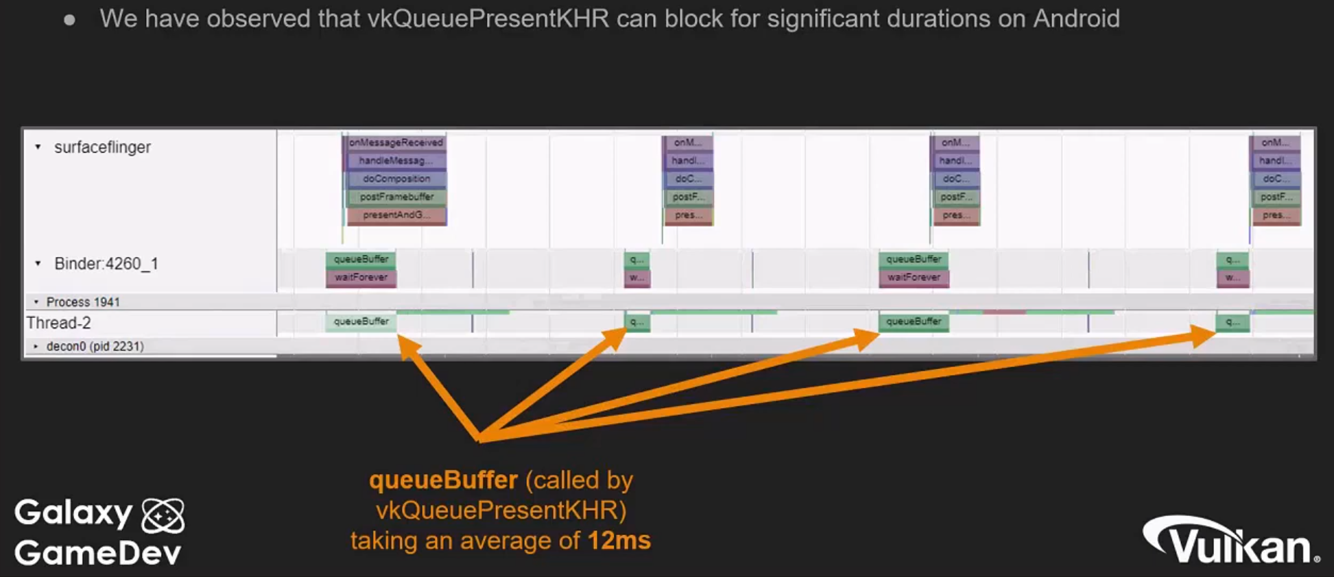 .
.
-
Android ideas for fixing Present blocking :
-
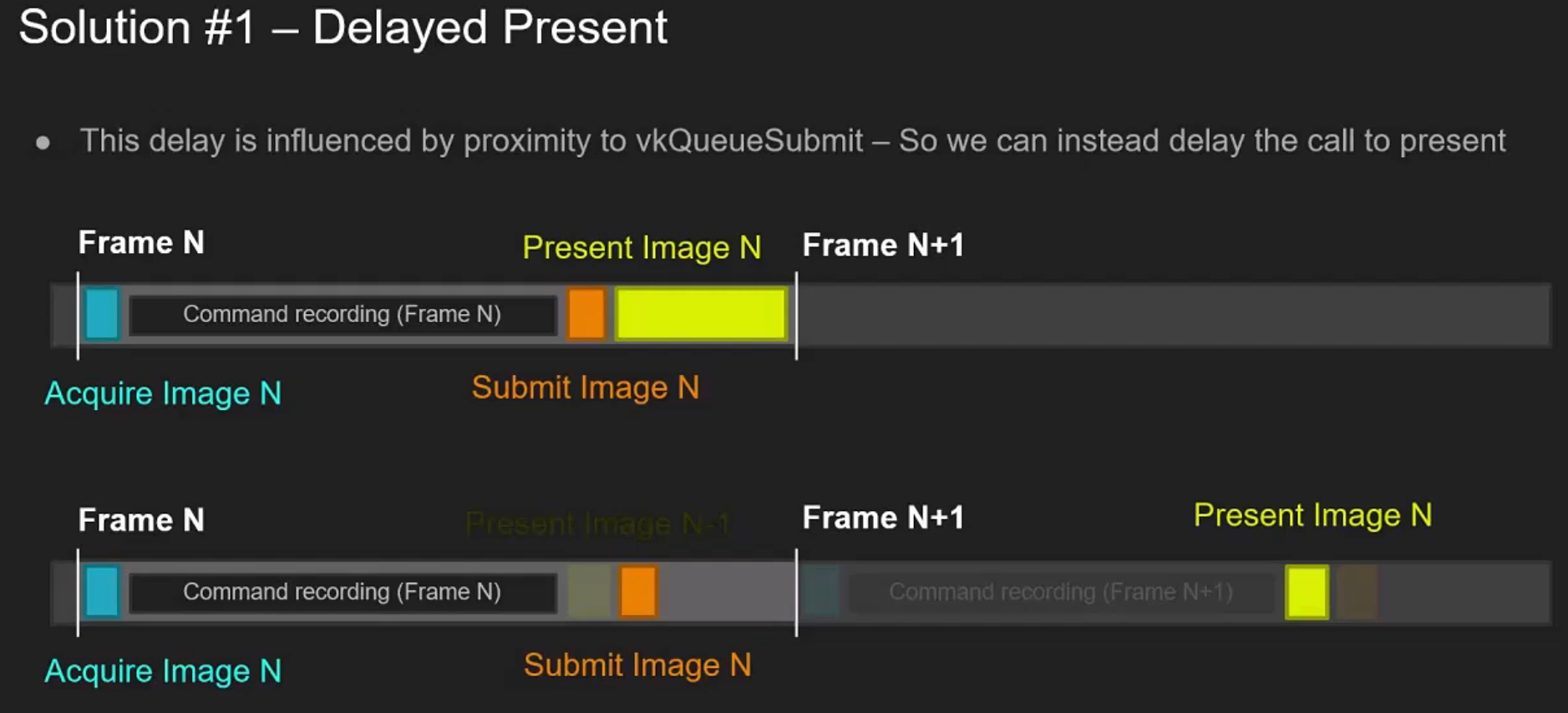 .
.
-
"This is not going to change when the image is presented, we are just delaying the calling of the function that would display the image, to a point where the image is more likely to be available by the GPU".
-
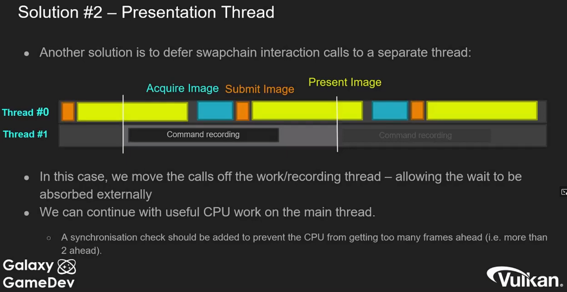 .
.
-
-
(2025-09-29) I watched it to study Pipeline Barriers, but the talk covers many mobile-specific topics.
-
GLFW
-
An unfortunate disadvantage is GLFW doesn’t work in Android or iOS; it is a desktop-only solution.
-
SDL does offer mobile support; however, mobile windowing support is best done by interfacing with the Operating system such as using the JNI in Android.
-
While mobile is beyond the scope of this initial tutorial, plans exist to eventually cover it in detail, and Google has excellent documentation .
Pre-Rotation
-
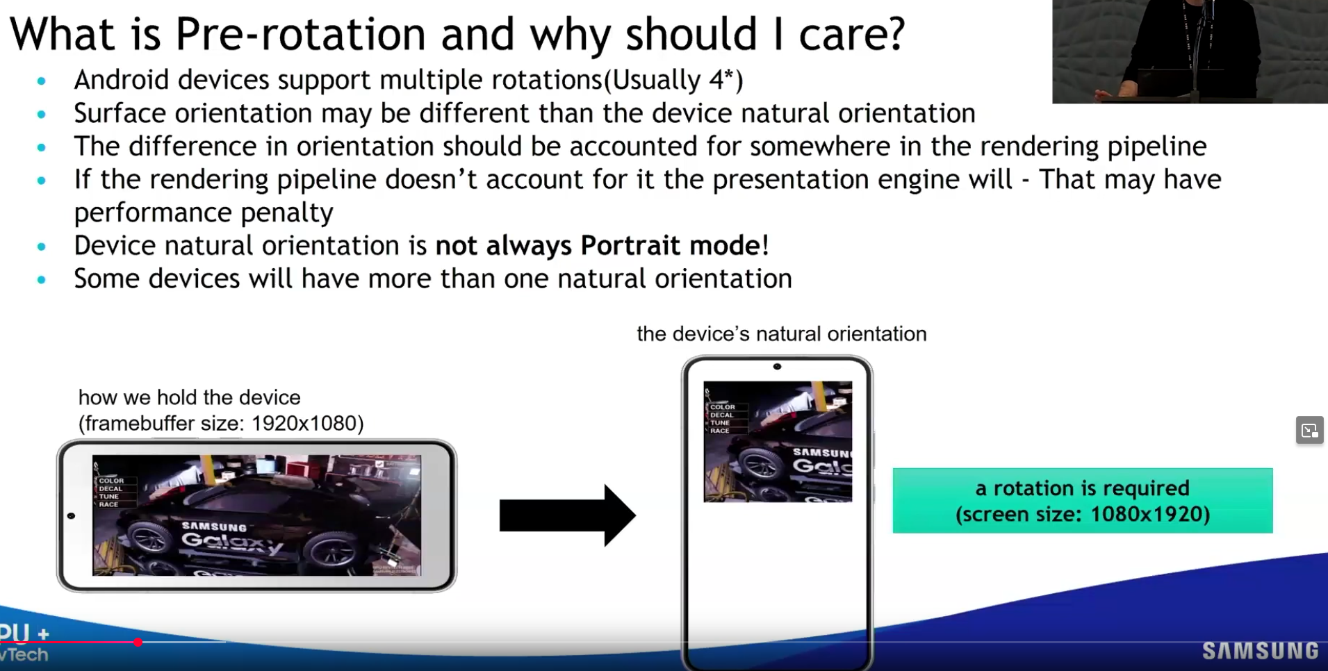 .
.
-
 .
.
-
You can only query
surfaceCapabilities.currentTransform, you cannot set it. -
If they don't match, the presentation engine will have to do the pre-rotation for you, which has a performance cost.
-
-
Implementing a full pre-rotate system is reportedly difficult, so many engines avoid it.
-
 .
.
-
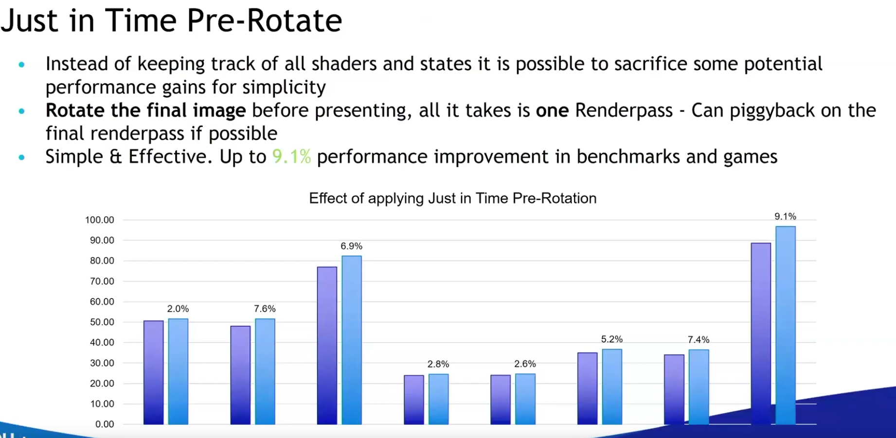 .
.
-
This is a simpler option to implement.
-
"Many engines already do a blit to the final image to the swapchain image, so this is the perfect place to do the pre-rotation".
-
"Basically free and you get performance benefits".
-
-
VR
Video Decoding
SPIR-V
-
Standard Portable Intermediate Representation V .
-
SPIR-V .
-
Vulkan’s official shader format (portable, efficient).
-
SPIR-V is a binary format.
-
Works with Metal via MoltenVK.
Compiling
-
You can write GLSL or HLSL and compile to SPIR-V.
-
GLSL to SPIR-V:
-
glslangValidator (from Khronos)
# Compile GLSL → SPIR-V (Vulkan) glslangValidator -V vertex_shader.vert -o vert.spv glslangValidator -V fragment_shader.frag -o frag.spv -
-
HLSL to SPIR-V:
-
DXC (DirectX Shader Compiler)
dxc -T vs_6_0 -E VSMain -spirv shader.hlsl -Fo vert.spv-
Requires HLSL shaders with Vulkan-compatible semantics.
-
-
Convert SPIR-V to other formats:
-
SPIRV-Cross (converts HLSL to GLSL/SPIR-V)
-
-
-
Compiling shaders on the commandline is one of the most straightforward options and it's the one that we'll use in this tutorial, but it's also possible to compile shaders directly from your own code.
-
The Vulkan SDK includes libshaderc , which is a library to compile GLSL code to SPIR-V from within your program.
-
Advantages
-
The advantage of using a bytecode format is that the compilers written by GPU vendors to turn shader code into native code are significantly less complex. The past has shown that with human-readable syntax like GLSL, some GPU vendors were rather flexible with their interpretation of the standard. If you happen to write non-trivial shaders with a GPU from one of these vendors, then you’d risk another vendor’s drivers rejecting your code due to syntax errors, or worse, your shader running differently because of compiler bugs. With a straightforward bytecode format like SPIR-V that will hopefully be avoided.
Tooling
spirv-cross
-
Cross-compilation
-
Converts SPIR-V shader binaries into high-level shading languages:
-
GLSL (various versions)
-
HLSL
-
MSL (Metal Shading Language for Apple platforms)
-
WGSL (WebGPU shading language)
-
-
This lets you write shaders once (e.g. in GLSL or HLSL), compile to SPIR-V, then regenerate source for other backends.
-
-
Reflection
-
Inspects SPIR-V binaries and reports metadata about:
-
Descriptor sets and bindings
-
Push constants
-
Vertex input/output attributes
-
Specialization constants
-
-
With the
--reflectflag, it outputs this data as JSON , making it easy to drive engine code-generation or runtime Vulkan setup.
-
-
Ex :
-
spirv-cross scene_vert.spv --reflect > scene_vert.json.
-
Web
-
No Vulkan support in browsers; you must port to WebGPU or use translation layers.
WebGPU (wgpu)
-
WebGPU is a cross-platform graphics API, aiming to unify GPU access across:
-
Browsers (via native support)
-
Native apps (via libraries like wgpu, Dawn, etc.)
-