-
Simple:
-
 .
.
-
-
Overall:
-
 .
.
-
-
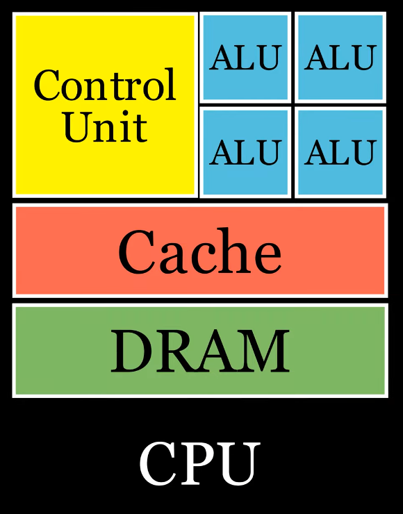
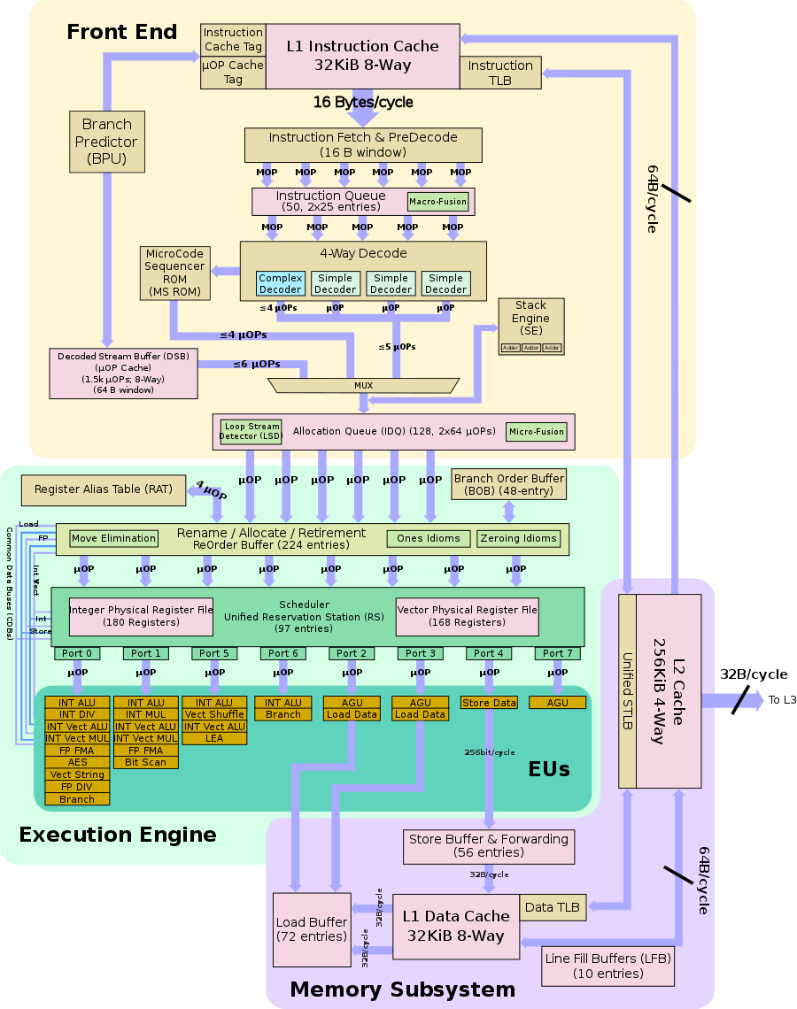
Skylake Block Diagram:
-
 .
.
-
This is not a pipeline diagram, it doesn't tell us how the chip works. It just a logical flow, some rough directions.
-
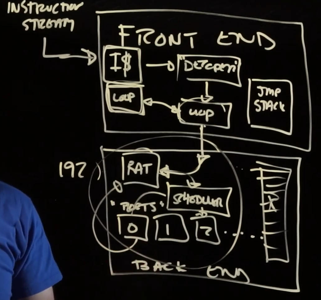
Front-end
-
"Figure out what to run".
-
Instruction stream :
-
Assembly code.
-
-
I$ :
-
micro ops / u OPs / μOP :
-
In the past, instructions were executed right away, but now they are decoded into smaller instructions: micro ops.
-
Analysis with Compiler Explorer and UICA .
-
{29:10} Show the usage of this site above.
-
UICA (Uops Info Code Analyzer), it's a tool to get a complete analysis of how the port brake down will go for your program.
-
There's also some graphs and execution traces.
-
"Predicted Throughput": you can use this to estimate how many cycles your loops is going to take.
-
-
-
-
Decoder :
-
Get the instructions from the instruction stream and decode them into micro ops.
-
"If we can shrink the size of our stream down, this might be a win for the act of getting the streams".
-
-
Loop cache / Trace cache :
-
Stores the result of decoding. It remembers the micro ops.
-
Sometimes decoding instructions can actually be the bottleneck in loops where the instructions are cheap to execute.
-
-
All the a "jump" does is tell us where to get more instructions, so we don't want to send that to the backend. For that reason, the frontend also handles jmp, stack, etc.
-
The reason for having branch prediction is so the chip doesn't halt waiting for the backend to finish just to finally know there was a branch, while the frontend was starving doing nothing. The backend is much more latent. The frontend tries to predict the branching to avoid this.
Back-end
-
Ports / execution units :
-
"Port is kind of a weird hardware term that doesn't give more intuition of what they do".
-
They are things that can do work.
-
If you want to add things together, one or more of these ports has a "adder" circuit in it.
-
-
RAT (register alias/allocation table) :
-
See below in 'Register -> Register Renaming'
-
-
Scheduler :
-
"Only wait if the things you need are still being worked on". For that reason it has to keep track of where things are, this is what the Scheduler does.
-
-
Retirement Buffer :
-
The micro ops are always retired in order. It writes micro ops in as they are finished in the slot where the need to go, so they are retired in the order they came in.
-
Manufacturing
-
-
Absurdly complicated, but at the same time "simple".
-
Very interesting.
-