-
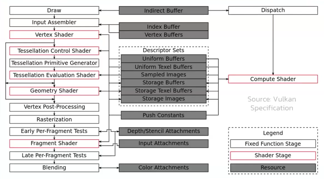
The graphics pipeline is required for all common drawing operations.
-
Holds the state of the GPU needed to draw. For example: shaders, rasterization options, depth settings.
-
It describes the configurable state of the graphics card, like the viewport size and depth buffer operation and the programmable state using VkShaderModule objects.
Stages
-
 .
.
-
 .
.
-
Disabling stages :
-
The tessellation and geometry stages can be disabled if you are just drawing simple geometry.
-
If you are only interested in depth values, then you can disable the fragment shader stage, which is useful for shadow map generation.
-
-
Fixed-function stages :
-
Allow you to tweak their operations using parameters, but the way they work is predefined.
-
Dynamic State :
-
While most of the pipeline state needs to be baked into the pipeline state, a limited amount of the state can actually be changed without recreating the pipeline at draw time.
-
Examples are the size of the viewport, line width and blend constants.
-
If you want to use dynamic state and keep these properties out, then you’ll have to fill in a
VkPipelineDynamicStateCreateInfostruct. -
This will cause the configuration of these values to be ignored , and you will be able (and required) to specify the data at drawing time.
-
This results in a more flexible setup and is widespread for things like viewport and scissor state, which would result in a more complex setup when being baked into the pipeline state.
-
-
-
Programmable stages :
-
Means that you can upload your own code to the graphics card to apply exactly the operations you want.
-
This allows you to use fragment shaders, for example, to implement anything from texturing and lighting to ray tracers. These programs run on many GPU cores simultaneously to process many objects, like vertices and fragments in parallel.
-
-
Immutability :
-
Is almost completely immutable, so you must recreate the pipeline from scratch if you want to change shaders, bind different framebuffers or change the blend function.
-
The disadvantage is that you’ll have to create a number of pipelines (many VkPipeline objects) that represent all the different combinations of states you want to use in your rendering operations. However, because all the operations you’ll be doing in the pipeline are known in advance, the driver can optimize for it much better.
-
Runtime performance is more predictable because large state changes like switching to a different graphics pipeline are made very explicit.
-
-
Only some basic configuration, like viewport size and clear color, can be changed dynamically.
-
Shader Compilation
Shader Module
-
A
VkShaderModuleis a processed shader file. -
We create it from a pre-compiled SPIR-V file.
-
We can call
vkDestroyShaderModuleafter they are used for the graphics pipeline creation.
Input Assembly
-
Fixed-function stage.
-
Collects the raw vertex data from the buffers you specify and may also use an index buffer to repeat certain elements without having to duplicate the vertex data itself.
-
VkPipelineVertexInputStateCreateInfo-
Describes the format of the vertex data that will be passed to the vertex shader.
-
pVertexBindingDescriptions-
Spacing between data and whether the data is per-vertex or per-instance (see instancing ).
-
-
pVertexAttributeDescriptions-
Type of the attributes passed to the vertex shader, which binding to load them from and at which offset.
-
-
-
VkPipelineInputAssemblyStateCreateInfo.-
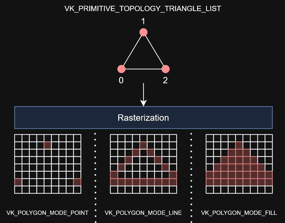
Describes two things: what kind of geometry will be drawn from the vertices and if primitive restart should be enabled.
-
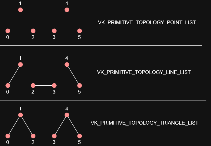
topology-
PRIMITIVE_TOPOLOGY_POINT_LIST-
points from vertices
-
-
PRIMITIVE_TOPOLOGY_LINE_LIST-
line from every two vertices without reuse
-
-
PRIMITIVE_TOPOLOGY_LINE_STRIP-
the end vertex of every line is used as start vertex for the next line
-
-
PRIMITIVE_TOPOLOGY_TRIANGLE_LIST-
triangle from every three vertices without reuse
-
-
PRIMITIVE_TOPOLOGY_TRIANGLE_STRIP-
the second and third vertex of every triangle is used as first two vertices of the next triangle
-
-
-
primitiveRestartEnable-
Normally, the vertices are loaded from the vertex buffer by index in sequential order, but with an element buffer you can specify the indices to use yourself.
-
This allows you to perform optimizations like reusing vertices.
-
-
If you set this to
TRUE, then it’s possible to break up lines and triangles in the_STRIPtopology modes by using a special index of0xFFFFor0xFFFFFFFF.
-
-
Primitive Topology
-
 .
.
Removing Input Attributes
VkPipelineVertexInputStateCreateInfo vertexInput = {
    .sType = VK_STRUCTURE_TYPE_PIPELINE_VERTEX_INPUT_STATE_CREATE_INFO,
    .vertexBindingDescriptionCount   = 0,
    .pVertexBindingDescriptions      = NULL,
    .vertexAttributeDescriptionCount = 0,
    .pVertexAttributeDescriptions    = NULL,
};
-
Input assembly still required:
.topology = VK_PRIMITIVE_TOPOLOGY_TRIANGLE_LIST
Vertex Shader
-
Programmable stage.
-
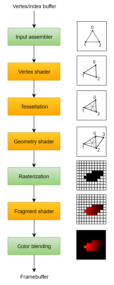
Is run for every vertex and generally applies transformations to turn vertex positions from model space to screen space. It also passes per-vertex data down the pipeline.
-
The
VkShaderModuleobjects are created from shader byte code. -
Accesses and computes one vertex at a time.
Tessellation Shader
-
Is run for every vertex and generally applies transformations to turn vertex positions from model space to screen space. It also passes per-vertex data down the pipeline.
-
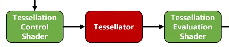
You can do tessellation in the Geometry Shader, but the Tessellation Shader is more appropriate and efficient.
-
 .
.
-
Sending this amount of vertices to the Vertex Shader would be quite more expensive than generating them in the Tessellation Shader.
-
-
 .
.
-
Tessellation Evaluation Shader.
-
Kinda like a Vertex Shader, after the Tessellation.
-
-
-
I was too lazy to watch it all.
-
The inputs are complicated, etc.
-
-
Tessellation output Execution Mode :
-
The tessellation evaluation stage will set either
Triangles,Quads, orIsolines
// Only 1 of the 3 is allowed layout(quads) in; layout(isolines) in; layout(triangles) in; -
Geometry Shader
-
Programmable stage.
-
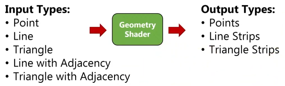
It operates on primitives .
-
Is run on every primitive (triangle, line, point) and can discard it or output more primitives than came in. This is similar to the tessellation shader but much more flexible.
-
However, it is used little in today’s applications because the performance is not that good on most graphics cards except for Intel’s integrated GPUs.
-
Also, almost all geometry shader use cases can be replaced with a more modern Mesh shader pipeline, which like ray tracing is a wholly new pipeline solution, so it exists outside the standard graphics pipeline setup.
-
-
 .
.
-
-
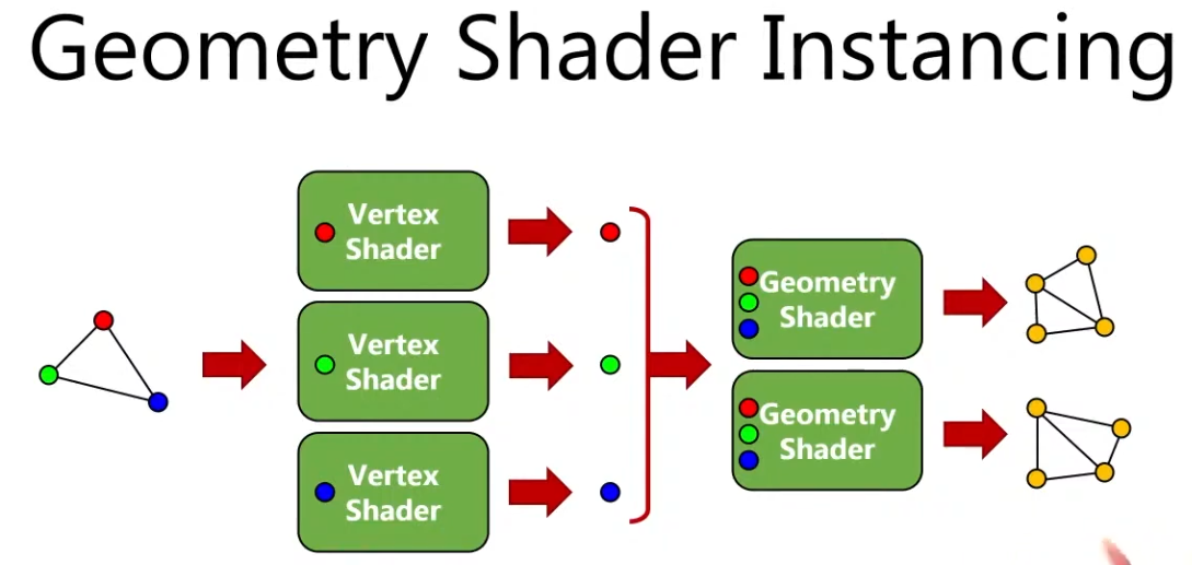
A Vertex Shader is more parallelized than a Geometry Shader.
-
A Vertex Shader computes one vertex at a time, while a geometry shader gets all the vertices that compose a primitive .
-
It does not have access to the whole mesh, just the vertices that compose the current primitive.
-
-
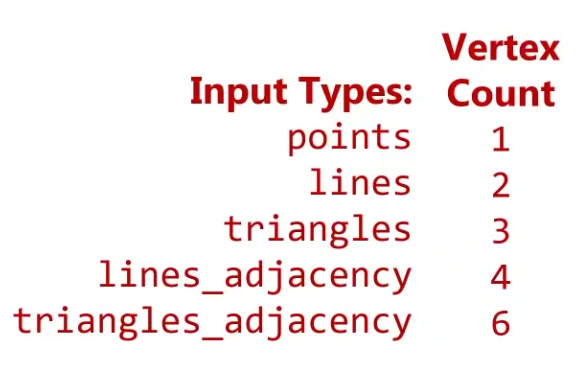
OpenGL Primitives :
-
May be useful.
-
 .
.
-
 .
.
-
-
Think of the Primitive Inputs as just the amount of vertices you are sending at a time.
-
 .
.
-
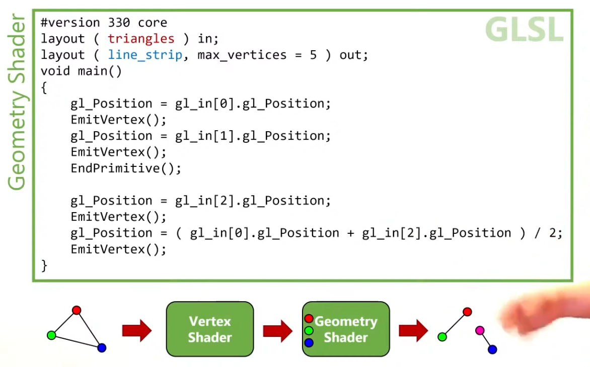
The reason for this is that you can get any primitive input and have any primitive output.
-
 .
.
-
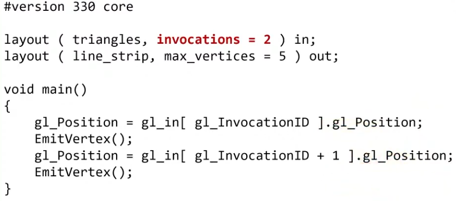
Use
EndPrimitive()so the line strips are separated.
-
-
 .
.
-
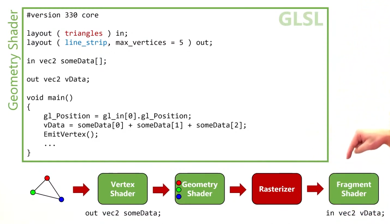
The Vertex Shader can output data to the Geometry Shader, in the form of an array.
-
The Geometry Shader can output data to the Fragment Shader, in a form of an interpolated value, using barycentric coordinates.
-
-
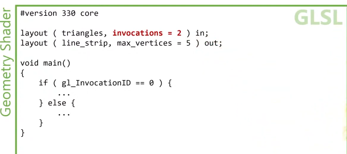
Instancing :
-
 .
.
-
You can have many instances of a Geometry Shader, where the input is the same but the output changes.
-
 .
.
-
 .
.
-
-
 .
.
-
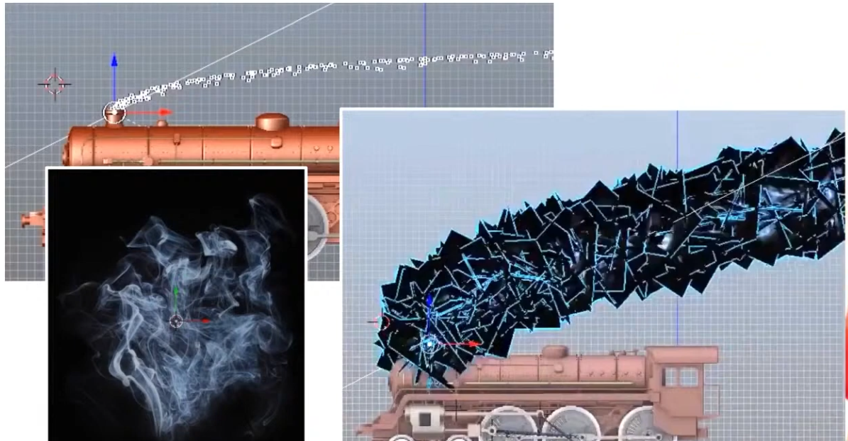
The smoke is a quad facing the camera (billboard).
-
The points are converted to quads.
-
-
 .
.
-
 .
.
-
Geometry output Execution Mode :
-
A geometry stage will set either
OutputPoints,OutputLineStrip, orOutputTriangleStrip
// Only 1 of the 3 is allowed layout(points) out; layout(line_strip) out; layout(triangle_strip) out; -
Rasterization
-
Fixed-function stage.
-
Breaks the primitives into fragments .
-
These are the pixel elements that they fill on the framebuffer.
-
Any fragments that fall outside the screen are discarded, and the attributes outputted by the vertex shader are interpolated across the fragments.
-
Fragments that are behind other primitive fragments can also be discarded here because of depth testing.
-
VkPipelineRasterizationStateCreateInfo.-
polygonMode -
lineWidth-
Is the width of rasterized line segments.
-
The maximum line width that is supported depends on the hardware.
-
Any line thicker than
1.0frequires you to enable thewideLinesGPU feature. -
If set to
0.0f, you get:lineWidthis 0.0, but the line width state is static (pCreateInfos[0].pDynamicState->pDynamicStatesdoes not containDYNAMIC_STATE_LINE_WIDTH) andwideLinesfeature was not enabled. The Vulkan spec states: If the pipeline requires pre-rasterization shader state, and thewideLinesfeature is not enabled, and no element of thepDynamicStatesmember ofpDynamicStateisDYNAMIC_STATE_LINE_WIDTH, the lineWidth member of pRasterizationState must be 1.0. -
So, set it to
1.0fby default.
-
-
cullMode-
NONE-
Specifies that no triangles are discarded
-
-
FRONT-
Specifies that front-facing triangles are discarded
-
-
BACK-
Specifies that back-facing triangles are discarded
-
-
FRONT_AND_BACK-
Specifies that all triangles are discarded.
-
-
Following culling, fragments are produced for any triangles which have not been discarded.
-
-
frontFace-
Specifies the vertex order for the faces to be considered front-facing.
-
COUNTER_CLOCKWISE-
Specifies that a triangle with positive area is considered front-facing.
-
-
CLOCKWISE-
Specifies that a triangle with negative area is considered front-facing.
-
-
Any triangle which is not front-facing is back-facing, including zero-area triangles.
-
-
rasterizerDiscardEnable.-
When enabled, primitives are discarded after they are processed by the last active shader stage in the pipeline before rasterization.
-
Controls whether primitives are discarded immediately before the rasterization stage. This is important because when this is set to
TRUEthe rasterization hardware is not executed. -
There are many Validation Usage errors that will not occur if this is set to
TRUEbecause some topology hardware is unused and can be ignored. -
Enabling this state is meant for very specific use cases. Prior to compute shaders, this was a common technique for writing geometry shader output to a buffer.
-
It can be used to debug/profile non-rasterization bottlenecks.
-
-
flags-
Reserved for future use.
-
-
depthClampEnable-
See the Depth section for details.
-
-
depthBiasEnable-
See the Depth section for details.
-
-
depthBiasConstantFactor-
See the Depth section for details.
-
-
depthBiasSlopeFactor-
See the Depth section for details.
-
-
depthBiasClamp-
See the Depth section for details.
-
-
Polygon Mode
-
 .
.
-
Determines how fragments are generated for geometry.
-
These modes affect only the final rasterization of polygons. The polygon’s vertices are shaded and the polygon is clipped and possibly culled before these modes are applied.
-
FILL-
Fill the area of the polygon with fragments.
-
-
LINE-
Polygon edges are drawn as lines
-
-
POINT-
Polygon vertices are drawn as points
-
If
VkPhysicalDeviceMaintenance5Properties::polygonModePointSizeisTRUE, the point size of the final rasterization of polygons is taken fromPointSize. -
Otherwise, the point size of the final rasterization of polygons is 1.0.
-
-
FILL_RECTANGLE_NV-
Specifies that polygons are rendered using polygon rasterization rules, modified to consider a sample within the primitive if the sample location is inside the axis-aligned bounding box of the triangle after projection.
-
Note that the barycentric weights used in attribute interpolation can extend outside the range
[0,1]when these primitives are shaded. -
Special treatment is given to a sample position on the boundary edge of the bounding box. In such a case, if two rectangles lie on either side of a common edge (with identical endpoints) on which a sample position lies, then exactly one of the triangles must produce a fragment that covers that sample during rasterization.
-
Polygons rendered in
FILL_RECTANGLE_NVmode may be clipped by the frustum or by user clip planes. If clipping is applied, the triangle is culled rather than clipped. -
Area calculation and facingness are determined for
FILL_RECTANGLE_NVmode using the triangle’s vertices.
-
-
If you have a vertex shader that has
PRIMITIVE_TOPOLOGY_TRIANGLE_LISTinput and then during rasterization usesPOLYGON_MODE_LINE, the effective topology is the Line Topology Class at that time. This means something likelineWidthwould be applied when filling in the polygon withPOLYGON_MODE_LINE.
Fragment Operations
Order
-
Discard rectangles test
-
Scissor test
-
Exclusive scissor test
-
Sample mask test
-
Certain Fragment shading operations:
-
Sample Mask Accesses
-
Tile Image Reads
-
Depth Replacement
-
Stencil Reference Replacement
-
Interlocked Operations
-
-
Multisample coverage
-
Depth bounds test
-
Stencil test
-
Depth test
-
Representative fragment test
-
Sample counting
-
Coverage to color
-
Coverage reduction
-
Coverage modulation
Early Per-Fragment Tests
-
OpenGL 4.6:
-
Once fragments are produced by rasterization, a number of per-fragment operations are performed prior to fragment shader execution. If a fragment is discarded during any of these operations, it will not be processed by any subsequent Stage, including fragment shader execution.
-
Three fragment operations are performed, and a further three are optionally performed on each fragment, in the following order:
-
the pixel ownership test (see section 14.9.1);
-
the scissor test (see section 14.9.2);
-
multisample fragment operations (see section 14.9.3);
-
-
If early per-fragment operations are enabled, these tests are also performed:
-
the stencil test (see section 17.3.3);
-
the depth buffer test (see section 17.3.4);
-
The depth buffer test discards the incoming fragment if a depth comparison fails. The comparison is enabled or disabled with the generic Enable and Disable commands using target DEPTH_TEST. When disabled, the depth comparison and subsequent possible updates to the depth buffer value are bypassed and the fragment is passed to the next operation. The stencil value, however, is modified as indicated below as if the depth buffer test passed. If enabled, the comparison takes place and the depth buffer and stencil value may subsequently be modified.
-
-
occlusion query sample counting (see section 17.3.5)
-
-
Early fragment tests, as an optimization, exist to prevent unnecessary executions of the Fragment Shader. If a fragment will be discarded based on the Depth Test (due perhaps to being behind other geometry), it saves performance to avoid executing the fragment shader. There is specialized hardware that makes this particularly efficient in many GPUs.
-
The most effective way to use early depth test hardware is to run a depth-only pre-processing pass. This means to render all available geometry, using minimal shaders and a rendering pipeline that only writes to the depth buffer. The Vertex Shader should do nothing more than transform positions, and the Fragment Shader does not even need to exist.
-
This provides the best performance gain if the fragment shader is expensive, or if you intend to use multiple passes across the geometry.
-
Limitations :
-
The Spec states that these operations happen after fragment processing. However, a specification only defines apparent behavior, so the implementation is only required to behave "as if" it happened afterwards.
-
Therefore, an implementation is free to apply early fragment tests if the Fragment Shader being used does not do anything that would impact the results of those tests. So if a fragment shader writes to glFragDepth, thus changing the fragment's depth value, then early testing cannot take place, since the test must use the new computed value.
-
Do recall that if a fragment shader writes to gl_FragDepth, even conditionally, it must write to it at least once on all codepaths.
-
There can be other hardware-based limitations as well. For example, some hardware will not execute an early depth test if the (deprecated) alpha test is active, as these use the same hardware on that platform. Because this is a hardware-based optimization, OpenGL has no direct controls that will tell you if early depth testing will happen.
-
Similarly, if the fragment shader discards the fragment with the discard keyword, this will almost always turn off early depth tests on some hardware. Note that even conditional use of discard will mean that the FS will turn off early depth tests.
-
All of the above limitations apply only to early testing as an optimization. They do not apply to anything below.
-
-
More recent hardware can force early depth tests, using a special fragment shader layout qualifier:
-
layout(early_fragment_tests).-
Vulkan:
-
Specifying is a way of the application programmer providing a promise to the implementation that it is algorithmically safe to kill the fragments, so you explicitly allow the change in application-visible behavior.
-
Specifying this will make per-fragment tests be performed before fragment shader execution. If this is not declared, per-fragment tests will be performed after fragment shader execution. Only one fragment shader (compilation unit) need declare this, though more than one can. If at least one declares this, then it is enabled.
-
-
OpenGL 4.6:
-
An explicit control is provided to allow fragment shaders to enable early fragment tests. If the fragment shader specifies the
early_fragment_testslayout qualifier, the per-fragment tests will be performed prior to fragment shader execution. Otherwise, they will be performed after fragment shader execution. -
This will also perform early stencil tests.
-
There is a caveat with this. This feature cannot be used to violate the sanctity of the depth test. When this is activated, any writes to
gl_FragDepthwill be ignored . The value written to the depth buffer will be exactly what was tested against the depth buffer: the fragment's depth computed through rasterization. -
This feature exists to ensure proper behavior when using Image Load Store or other incoherent memory writing . Without turning this on, fragments that fail the depth test would still perform their Image Load/Store operations, since the fragment shader that performed those operations successfully executed. However, with early fragment tests, those tests were run before the fragment shader. So this ensures that image load/store operations will only happen on fragments that pass the depth test.
-
Enabling this feature has consequences for the results of a discarded fragment.
-
-
-
-
Viewport and Scissors
-
A viewport basically describes the region of the framebuffer that the output will be rendered to.
-
Viewports define the transformation from the image to the framebuffer, scissor rectangles define in which region pixels will actually be stored. The rasterizer will discard any pixels outside the scissored rectangles. They function like a filter rather than a transformation.
-
The difference is illustrated below.
-
 .
.
-
Note that the left scissored rectangle is just one of the many possibilities that would result in that image, as long as it’s larger than the viewport.
-
So if we wanted to draw to the entire framebuffer, we would specify a scissor rectangle that covers it entirely:
vk::Rect2D{ vk::Offset2D{ 0, 0 }, swapChainExtent }
-
-
Parameters :
-
This will almost always be the rectangle
(0, 0),(width, height)and in this tutorial that will also be the case.-
Remember that the size of the Swapchain and its images may differ from the
WIDTHandHEIGHTof the window. -
The Swapchain images will be used as framebuffers later on, so we should stick to their size.
-
-
The
minDepthandmaxDepthvalues specify the range of depth values to use for the framebuffer. These values must be within the[0.0f, 1.0f]range, butminDepthmay be higher thanmaxDepth.-
If you aren’t doing anything special, then you should stick to the standard values of
0.0fand1.0f.
-
-
-
As a Dynamic State or Static State :
-
Viewport(s) and scissor rectangle(s) can either be specified as a static part of the pipeline or as a dynamic state set in the command buffer.
-
Independent of how you set them, it’s possible to use multiple viewports and scissor rectangles on some graphics cards, so the structure members reference an array of them. Using multiple requires enabling a GPU feature (see logical device creation).
-
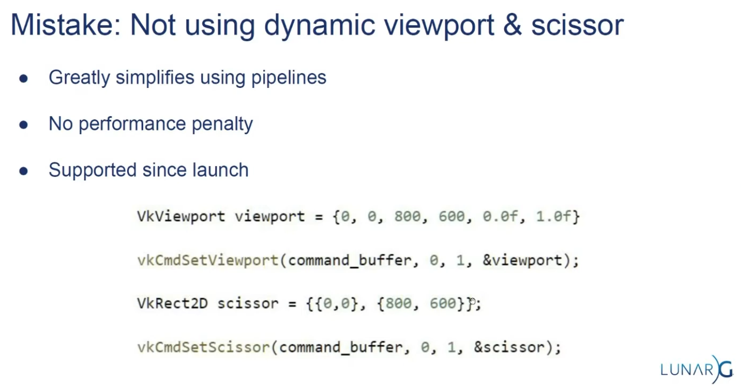
It’s often convenient to make viewport and scissor state dynamic as it gives you a lot more flexibility.
-
With dynamic state :
-
It’s even possible to specify different viewports and or scissor rectangles within a single command buffer.
-
This is widespread and all implementations can handle this dynamic state without a performance penalty.
-
When opting for dynamic viewport(s) and scissor rectangle(s), you need to enable the respective dynamic states for the pipeline:
std::vector dynamicStates = { vk::DynamicState::eViewport, vk::DynamicState::eScissor }; vk::PipelineDynamicStateCreateInfo dynamicState({}, dynamicStates.size(), dynamicStates.data()); -
And then you only need to specify their count at pipeline creation time:
vk::PipelineViewportStateCreateInfo viewportState({}, 1, {}, 1); -
The actual viewport(s) and scissor rectangle(s) will then later be set up at drawing time.
-
-
Without dynamic state:-
The viewport and scissor rectangle need to be set in the pipeline using the
VkPipelineViewportStateCreateInfostruct. This makes the viewport and scissor rectangle for this pipeline immutable. Any changes required to these values would require a new pipeline to be created with the new values.
-
-
What should you use?
-
USE DYNAMIC. There's no performance penalty.
-
Supported since launch.
-
LunarG:
-
 .
.
-
-
-
Multi-Sampling
Setup
-
VkPipelineMultisampleStateCreateInfo.-
rasterizationSamples-
If the bound pipeline was created without a
VkAttachmentSampleCountInfoAMDorVkAttachmentSampleCountInfoNVstructure, and themultisampledRenderToSingleSampledfeature is not enabled, and the current render pass instance was begun withvkCmdBeginRenderingwith aVkRenderingInfo:colorAttachmentCountparameter greater than 0, then each element of theVkRenderingInfo:pColorAttachmentsarray with aimageViewnot equal toNULL_HANDLEmust have been created with a sample count equal to the value ofrasterizationSamplesfor the bound graphics pipeline. -
Is a VkSampleCountFlagBits value specifying the number of samples used in rasterization. This value is ignored for the purposes of setting the number of samples used in rasterization if the pipeline is created with the
DYNAMIC_STATE_RASTERIZATION_SAMPLES_EXTdynamic state set, but ifDYNAMIC_STATE_SAMPLE_MASK_EXTdynamic state is not set, it is still used to define the size of thepSampleMaskarray as described below.
-
-
sampleShadingEnable-
It can be used to enable Sample Shading .
-
-
minSampleShading-
Specifies a minimum fraction of sample shading if
sampleShadingEnableisTRUE.
-
-
pSampleMask-
Is a pointer to an array of
VkSampleMaskvalues used in the sample mask test .
-
-
alphaToCoverageEnable-
Controls whether a temporary coverage value is generated based on the alpha component of the fragment’s first color output as specified in the Multisample Coverage section.
-
-
alphaToOneEnable-
Controls whether the alpha component of the fragment’s first color output is replaced with one as described in Multisample Coverage .
-
-
flags-
Reserved for future use.
-
-
Resolving
-
-
resolveMode-
Is a VkResolveModeFlagBits value defining how data written to
imageViewwill be resolved intoresolveImageView. -
If
resolveModeis notRESOLVE_MODE_NONE, andresolveImageViewis not NULL_HANDLE , a render pass multisample resolve operation is defined for the attachment subresource. -
RESOLVE_MODE_NONE-
Specifies that no resolve operation is done.
-
-
RESOLVE_MODE_SAMPLE_ZERO-
Specifies that result of the resolve operation is equal to the value of sample 0.
-
-
RESOLVE_MODE_AVERAGE-
Specifies that result of the resolve operation is the average of the sample values.
-
-
RESOLVE_MODE_MIN-
Specifies that result of the resolve operation is the minimum of the sample values.
-
-
RESOLVE_MODE_MAX-
Specifies that result of the resolve operation is the maximum of the sample values.
-
-
RESOLVE_MODE_EXTERNAL_FORMAT_DOWNSAMPLE_ANDROID-
Specifies that rather than a multisample resolve, a single sampled color attachment will be downsampled into a Y′CBCR format image specified by an external Android format. Unlike other resolve modes, implementations can resolve multiple times during rendering, or even bypass writing to the color attachment altogether, as long as the final value is resolved to the resolve attachment. Values in the G, B, and R channels of the color attachment will be written to the Y, CB, and CR channels of the external format image, respectively. Chroma values are calculated as if sampling with a linear filter from the color attachment at full rate, at the location the chroma values sit according to VkPhysicalDeviceExternalFormatResolvePropertiesANDROID ::
externalFormatResolveChromaOffsetX, VkPhysicalDeviceExternalFormatResolvePropertiesANDROID ::externalFormatResolveChromaOffsetY, and the chroma sample rate of the resolved image. -
No range compression or Y′CBCR model conversion is performed by
RESOLVE_MODE_EXTERNAL_FORMAT_DOWNSAMPLE_ANDROID; applications have to do these conversions themselves. Value outputs are expected to match those that would be read through a Y′CBCR sampler usingSAMPLER_YCBCR_MODEL_CONVERSION_RGB_IDENTITY. The color space that the values should be in is defined by the platform and is not exposed via Vulkan.
-
-
-
resolveImageView-
Is an image view used to write resolved data at the end of rendering.
-
-
resolveImageLayout-
Is the layout that
resolveImageViewwill be in during rendering. -
If
imageViewis notNULL_HANDLEandresolveModeis notRESOLVE_MODE_NONE,resolveImageLayoutmust not beIMAGE_LAYOUT_UNDEFINED,IMAGE_LAYOUT_DEPTH_STENCIL_READ_ONLY_OPTIMAL,IMAGE_LAYOUT_SHADER_READ_ONLY_OPTIMAL,IMAGE_LAYOUT_TRANSFER_SRC_OPTIMAL,IMAGE_LAYOUT_ZERO_INITIALIZED_EXT,IMAGE_LAYOUT_TRANSFER_DST_OPTIMAL, orIMAGE_LAYOUT_PREINITIALIZED
-
-
-
From Multisample, to Singlesample.
-
Combine sample values from a single pixel in a multisample attachment and store the result to the corresponding pixel in a single sample attachment.
-
Multisample resolve operations for attachments execute in the
PIPELINE_STAGE_COLOR_ATTACHMENT_OUTPUTpipeline stage. A final resolve operation for all pixels in the render area happens-after any recorded command which writes a pixel via the multisample attachment to be resolved or an explicit alias of it in the subpass that it is specified. -
Any single sample attachment specified for use in a multisample resolve operation may have its contents modified at any point once rendering begins for the render pass instance.
-
Reads from the multisample attachment can be synchronized with
ACCESS_COLOR_ATTACHMENT_READ. Access to the single sample attachment can be synchronized withACCESS_COLOR_ATTACHMENT_READandCOLOR_ATTACHMENT_WRITE. These pipeline stage and access types are used whether the attachments are color or depth/stencil attachments. -
When using render pass objects, a subpass dependency specified with the above pipeline stages and access flags will ensure synchronization with multisample resolve operations for any attachments that were last accessed by that subpass. This allows later subpasses to read resolved values as input attachments.
-
Resolve operations only update values within the defined render area for the render pass instance. However, any writes performed by a resolve operation (as defined by its access masks) to a given attachment may read and write back any memory locations within the image subresource bound for that attachment. For depth/stencil images, if
separateDepthStencilAttachmentAccessisFALSE, writes to one aspect may also result in read-modify-write operations for the other aspect. If the subresource is bound to an attachment with feedback loop enabled , implementations must not access pixels outside of the render area. -
As entire subresources could be accessed by multisample resolve operations, applications cannot safely access values outside of the render area via aliased resources during a render pass instance when a multisample resolve operation is performed.
-
If
RESOLVE_MODE_AVERAGEis used, and the source format is a floating-point or normalized type, the sample values for each pixel are resolved with implementation-defined numerical precision. -
If the numeric format of the resolve attachment uses sRGB encoding, the implementation should convert samples from nonlinear to linear before averaging samples as described in the “sRGB EOTF” section of the Khronos Data Format Specification . In this case, the implementation must convert the linear averaged value to nonlinear before writing the resolved result to resolve attachment.
-
The resolve mode and store operation are independent; it is valid to write both resolved and unresolved values, and equally valid to discard the unresolved values while writing the resolved ones.
Multisampling Anti-Aliasing (MSAA)
-
Using only one sample per pixel which is equivalent to no multisampling.
-
Maximum supported :
-
Can be extracted from
VkPhysicalDevicePropertiesassociated with our selected physical device. -
The highest sample count that Color Image and Depth Image (Buffer) will be the maximum we can support.
-
-
What to Multisample :
-
The render target.
-
If using a depth image, it should also be multisampled.
-
-
Limitations :
-
The multisampled image should only have one mip level.
-
This is enforced by the Vulkan specification in case of images with more than one sample per pixel.
-
-
Multi-sampled images cannot be presented directly.
-
This requirement does not apply to the depth buffer, since it won’t be presented at any point.
-
-
-
DOs :
-
Use 4x MSAA if possible; it’s not expensive and provides good image quality improvements.
-
Use
loadOp = LOAD_OP_CLEARorloadOp = LOAD_OP_DONT_CAREfor multisampled images. -
Use
storeOp = STORE_OP_DONT_CAREfor multisampled images. -
Use
LAZILY_ALLOCATEDmemory to back the allocated multisampled images; they do not need to be persisted into main memory and therefore do not need physical backing storage. -
Use
pResolveAttachmentsin a subpass to automatically resolve a multisampled color buffer into a single-sampled color buffer. -
Use
KHR_depth_stencil_resolvein a subpass to automatically resolve a multisampled depth buffer into a single-sampled depth buffer. Typically this is only useful if the depth buffer is going to be used further, in most cases it is transient and does not need to be resolved.
-
-
Avoid :
-
Avoid using
vkCmdResolveImage(); this has a significant negative impact on bandwidth and performance. -
Avoid using
loadOp = LOAD_OP_LOADfor multisampled image attachments. -
Avoid using
storeOp = STORE_OP_STOREfor multisampled image attachments. -
Avoid using more than 4x MSAA without checking performance.
-
-
Impact :
-
Failing to get an inline resolve can result in substantially higher memory bandwidth and reduced performance.
-
Manually writing and resolving a 4x MSAA 1080p surface at 60 FPS requires 3.9GB/s of memory bandwidth compared to just 500MB/s when using an inline resolve.
-
-
-
Sample Shading :
-
There are certain limitations of our current MSAA implementation which may impact the quality of the output image in more detailed scenes. For example, we're currently not solving potential problems caused by shader aliasing, i.e. MSAA only smoothens out the edges of geometry but not the interior filling. This may lead to a situation when you get a smooth polygon rendered on screen but the applied texture will still look aliased if it contains high contrasting colors. One way to approach this problem is to enable Sample Shading which will improve the image quality even further, though at an additional performance cost:
void createLogicalDevice() { ... deviceFeatures.sampleRateShading = TRUE; // enable sample shading feature for the device ... } void createGraphicsPipeline() { ... multisampling.sampleShadingEnable = TRUE; // enable sample shading in the pipeline multisampling.minSampleShading = .2f; // min fraction for sample shading; closer to one is smoother ... }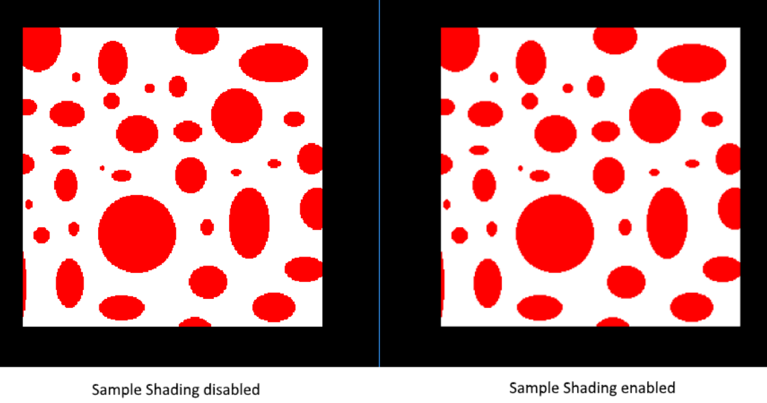 .
.
-
-
Performance Tests :
-
(2025-09-07)
-
Done anyway, very approximate.
-
-
MSAAx8 = 900 fps
-
MSAAx4 = 1250fps
-
MSAAx2 = 1550fps
-
MSAA off = 2100fps
-
As samples increase, frame time increases approximately by factors 1.35 (x2), 1.68 (x4) and 2.33 (x8) compared to the case without MSAA — this is consistent with substantial per-sample cost increase, but is not strictly linear with the number of samples (e.g.: x4 is not exactly 4× nor x8 exactly 8×).
-
Fragment Shader
-
Programmable stage.
-
Is invoked for every fragment that survives and determines which framebuffer(s) the fragments are written to and with which color and depth values. It can do this using the interpolated data from the vertex shader, which can include things like texture coordinates and normals for lighting.
-
The
VkShaderModuleobjects are created from shader byte code.
Color Blending
-
Fixed-function stage.
-
Controls how the GPU combines the fragment shader’s output with what is already in the framebuffer.
-
Applies operations to mix different fragments that map to the same pixel in the framebuffer. Fragments can simply overwrite each other, add up or be mixed based upon transparency.
-
After a fragment shader has returned a color, it needs to be combined with the color that is already in the framebuffer.
-
This transformation is known as color blending, and there are two ways to do it:
-
Mix the old and new value to produce a final color
-
Combine the old and new value using a bitwise operation
-
-
Example :
-
If enabled blending in the pipeline, it will blend the frag shader result with the render_target previous visual.
-
So if the frag result has alpha < 1.0, it will blend the clear color with the frag shader result, giving it a "transparent visual" against the clear color.
-
-
vkPipelineColorBlendAttachmentState.-
Contains the configuration per attached framebuffer.
-
This per-framebuffer struct allows you to configure the first way of color blending:
// Pseudo-code if (blendEnable) { finalColor.rgb = (srcColorBlendFactor * newColor.rgb) <colorBlendOp> (dstColorBlendFactor * oldColor.rgb); finalColor.a = (srcAlphaBlendFactor * newColor.a) <alphaBlendOp> (dstAlphaBlendFactor * oldColor.a); } else { finalColor = newColor; } finalColor = finalColor & colorWriteMask; -
The most common way to use color blending is to implement alpha blending, where we want the new color to be blended with the old color based on its opacity.
-
The
finalColorshould then be computed as follows:finalColor.rgb = newAlpha * newColor + (1 - newAlpha) * oldColor; finalColor.a = newAlpha.a; -
This can be achieved with the following parameters:
colorBlendAttachment.blendEnable = vk::True;
colorBlendAttachment.srcColorBlendFactor = vk::BlendFactor::eSrcAlpha;
colorBlendAttachment.dstColorBlendFactor = vk::BlendFactor::eOneMinusSrcAlpha;
colorBlendAttachment.colorBlendOp = vk::BlendOp::eAdd;
colorBlendAttachment.srcAlphaBlendFactor = vk::BlendFactor::eOne;
colorBlendAttachment.dstAlphaBlendFactor = vk::BlendFactor::eZero;
colorBlendAttachment.alphaBlendOp = vk::BlendOp::eAdd;
-
-
blendEnable-
If set to
FALSE, then the new color from the fragment shader is passed through unmodified. Otherwise, the two mixing operations are performed to compute a new color. -
The resulting color is AND’d with the
colorWriteMaskto determine which channels are actually passed through.
-
-
-
VkPipelineColorBlendStateCreateInfo.-
Contains the global color blending settings.
-
References the array of structures for all the framebuffers and allows you to set blend constants that you can use as blend factors in the aforementioned calculations.
-
attachmentCount-
Is the number of
VkPipelineColorBlendAttachmentStateelements inpAttachments. -
It is ignored if the pipeline is created with
DYNAMIC_STATE_COLOR_BLEND_ENABLET,DYNAMIC_STATE_COLOR_BLEND_EQUATION_EXT, andDYNAMIC_STATE_COLOR_WRITE_MASK_EXTdynamic states set, and eitherDYNAMIC_STATE_COLOR_BLEND_ADVANCED_EXTset or the advancedBlendCoherentOperations feature is not enabled.
-
-
pAttachments-
Is a pointer to an array of
VkPipelineColorBlendAttachmentStatestructures defining blend state for each color attachment. -
It is ignored if the pipeline is created with
DYNAMIC_STATE_COLOR_BLEND_ENABLET,DYNAMIC_STATE_COLOR_BLEND_EQUATION_EXT, andDYNAMIC_STATE_COLOR_WRITE_MASK_EXTdynamic states set, and eitherDYNAMIC_STATE_COLOR_BLEND_ADVANCED_EXTset or the advancedBlendCoherentOperations feature is not enabled.
-
-
logicOpEnable-
Controls whether to apply Logical Operations .
-
-
logicOp-
Selects which logical operation to apply.
-
If you want to use the second method of blending (a bitwise combination), then you should set
logicOpEnabletoTRUE.-
Note that this will automatically disable the first method, as if you had set
blendEnabletoFALSEfor every attached framebuffer.
-
-
colorWriteMaskwill also be used in this mode to determine which channels in the framebuffer will actually be affected. -
If disabled both modes, the fragment colors will be written to the framebuffer unmodified.
-
-
blendConstants-
Is a pointer to an array of four values used as the R, G, B, and A components of the blend constant that are used in blending, depending on the blend factor .
-
-
flags
-
Creation
Setup
-
vkGraphicsPipelineCreateInfo.-
flags-
DISABLE_OPTIMIZATION-
Specifies that the created pipeline will not be optimized.
-
Using this flag may reduce the time taken to create the pipeline.
-
-
-
renderPass-
Is set to
nullptrbecause we’re using dynamic rendering instead of a traditional render pass.
-
-
basePipelineHandle -
basePipelineIndex -
Graphics Pipelines Inheritance :
-
Vulkan allows you to create a new graphics pipeline by deriving from an existing pipeline.
-
The idea of pipeline derivatives is that it is less expensive to set up pipelines when they have much functionality in common with an existing pipeline and switching between pipelines from the same parent can also be done quicker.
-
You can either specify the handle of an existing pipeline with
basePipelineHandleor reference another pipeline that is about to be created by index withbasePipelineIndex. -
These values are only used if the
VPIPELINE_CREATE_DERIVATIVEflag is also specified in theflagsfield ofVkGraphicsPipelineCreateInfo.
-
-
-
-
device-
Is the logical device that creates the graphics pipelines.
-
-
pipelineCache-
Is either
NULL_HANDLE, indicating that pipeline caching is disabled, or to enable caching, the handle of a valid VkPipelineCache object. The implementation must not access this object outside of the duration of this command. -
A pipeline cache can be used to store and reuse data relevant to pipeline creation across multiple calls to
vkCreateGraphicsPipelinesand even across program executions if the cache is stored to a file. This makes it possible to significantly speed up pipeline creation at a later time.
-
-
createInfoCount-
Is the length of the
pCreateInfosandpPipelinesarrays.
-
-
pCreateInfos-
Is a pointer to an array of VkGraphicsPipelineCreateInfo structures.
-
-
pAllocator-
Controls host memory allocation as described in the Memory Allocation chapter.
-
-
pPipelines-
Is a pointer to an array of VkPipeline handles in which the resulting graphics pipeline objects are returned.
-
-
Dynamic Rendering Extra Steps
-
Changes to the
vkGraphicsPipelineCreateInfo:-
The
vkGraphicsPipelineCreateInfomust be created without aVkRenderPass. -
The
VkPipelineRenderingCreateInfomust be included in thepNext.-
If a graphics pipeline is created with a valid
VkRenderPass, the parameters of theVkPipelineRenderingCreateInfoare ignored.
-
-
-
VkPipelineRenderingCreateInfo.-
colorAttachmentCount-
Is the number of entries in
pColorAttachmentFormats
-
-
pColorAttachmentFormats-
Is a pointer to an array of
VkFormatvalues defining the format of color attachments used in this pipeline.
-
-
depthAttachmentFormat-
Is a
VkFormatvalue defining the format of the depth attachment used in this pipeline.
-
-
stencilAttachmentFormat-
Is a
VkFormatvalue defining the format of the stencil attachment used in this pipeline.
-
-
viewMask-
Is a bitfield of view indices describing which views are active during rendering.
-
It must match VkRenderingInfo.viewMask when rendering.
-
As defined in
VkRenderingInfo:-
Is a bitfield of view indices describing which views are active during rendering, when it is not
0. -
If
viewMaskis not0, multiview is enabled.
-
-
-
-
Formats :
-
If
depthAttachmentFormat,stencilAttachmentFormat, or any element ofpColorAttachmentFormatsisUNDEFINED, it indicates that the corresponding attachment is unused within the render pass. -
Valid formats indicate that an attachment can be used - but it is still valid to set the attachment to
NULLwhen beginning rendering.
-
-
Managing Pipelines and Reducing overhead
-
Tips and Tricks: Vulkan Dos and Don’ts .
-
Use pipeline cache.
-
Use specialization constants.
-
This may cause a possible decrease in the number of instructions and registers used by the shader.
-
Specialization constants can also be used instead of offline shader permutations to minimize the amount of bytecode that needs to be shipped with an application.
-
-
Switching pipelines:
-
Avoid frequently switching between pipelines that use different sets of pipeline stages.
-
Minimize the number of
vkCmdBindPipelinecalls, each call has significant CPU cost and GPU cost.-
Consider sorting of drawcalls and/or using a low number of dynamic states.
-
-
Switching on/off the tessellation, geometry, task and mesh shaders is an expensive operation.
-
-
Draw calls:
-
Group draw calls, taking into account what kinds of shaders they use.
-
-
The Problem
-
Immutable Pipelines.
-
Each combination of inputs require a dedicated pipeline.
-
Shader, topology, blend mode, vertex layout, cull mode, etc.
-
So if we want to do things like toggle depth-testing on and off, we will need 2 pipelines.
-
-
Causes a combinatorial explosion of variants.
-
10.000's of pipelines for shipping titles.
-
-
Building pipelines is a very expensive operation, and we want to minimize the number of pipelines used as its critical for performance.
My decisions
-
(2025-08-10)
-
Dynamic State is a must.
-
The use of Shader Object still seems new and may introduce some extra complexity in certain cases.
-
I don't know about mobile support.
-
-
The use of Graphics Pipeline Libraries sounds interesting, but at the same time it seems limiting in some moments, for Geometry and Tessellation Shaders.
-
I don't know about mobile support.
-
-
Overall, I believe that refactoring a game object to use Shader Object or Graphics Pipeline Libraries sounds "simple", since it's more about how the pipeline is constructed than how one interacts with shaders or descriptor sets. In other words, it seems like an okay decision to make in the future.
-
Considering the low support, and the fact that I don't have so many pipelines in mind that actually make these solutions necessary, I prefer to use graphics pipelines manually, in the "default" way.
-
Regardless, I believe that using Shader Object or Graphics Pipeline does not remove the need to worry about pipeline caching or precautions to avoid switching the pipeline binding all the time.
-
Correct. Extensions change how pipelines are created/linked but do not remove the performance considerations around pipeline creation, pipeline cache usage, or minimizing pipeline re-binding at draw time. Vendors and platform docs recommend pipeline caches, pre-creation, and minimizing pipeline binds.
-
-
What I will do, therefore: caching and sorting of pipelines based on similarity. I will worry more about binding the pipeline in command buffers and their descriptor sets, than the process of facilitating the creation of new pipelines.
-
This plan aligns with widely recommended practical strategies: use pipeline caches (persist to disk where possible), sort and batch by pipeline/descriptor similarity, and create pipelines asynchronously (background threads) to avoid stutter. These practices address the main runtime pain points regardless of whether you later adopt shader-object or pipeline-library extensions.
-
Your current decisions are internally consistent and align with common, pragmatic industry practice: prefer stable/default graphics pipelines with pipeline caching, sorting, and background creation as the primary strategy, while keeping code organized so you can adopt
EXT_shader_objectorEXT_graphics_pipeline_librarylater if/when device support and measured benefits justify the switch.
-
Mutability with
VkDynamicState
-
Implemented.
-
It's a must .
-
Not everything has to be immutable.
-
Set desired state while recording command buffers.
-
Over 70 states can be dynamic.
-
If we don't use this, we would need to create new pipelines if we wanted to change the resolution of our rendering.
No pipelines, with
EXT_shader_object
-
Sample .
-
Article .
-
Support :
-
Coverage .
-
(2025-09-08) 11.29%.
-
33.8% Windows.
-
26.3% Linux.
-
0% Android.
-
-
-
Shader Object and implementation in Odin {7:30 -> 11:56} .
-
Questions :
-
I don't know where
pColorAttachmentFormatsanddepthAttachmentFormatare specified.-
I don't know if it's even necessary to specify them anywhere.
-
The words
attachmentorformatdo not appear anywhere in the sample or in the spec of the extension.
-
pipeline_rendering_create_info := vk.PipelineRenderingCreateInfo{ sType = .PIPELINE_RENDERING_CREATE_INFO, colorAttachmentCount = 1, pColorAttachmentFormats = format, depthAttachmentFormat = .D24_UNORM_S8_UINT, stencilAttachmentFormat = {}, viewMask = 0, } -
-
Code .
create_shaders :: proc() { push_constant_ranges := []vk.PushConstantRange { // Pipeline { stageFlags = {.VERTEX, .FRAGMENT}, size = 128, } } /* This is not used in the Shader Object. The only place that needs this in its code, is when making the call `vk.CmdPushConstants(cmd, g.pipeline_layout, {.VERTEX, .FRAGMENT}, 0, size_of(push), &push)`. */ pipeline_layout_ci := vk.PipelineLayoutCreateInfo { sType = .PIPELINE_LAYOUT_CREATE_INFO, // flags = {}, // setLayoutCount = 1, // pSetLayouts = {}, pushConstantRangeCount = u32(len(push_constant_ranges)), pPushConstantRanges = raw_data(push_constant_ranges), } check(vk.CreatePipelineLayout(g.device, &pipeline_layout_ci, nil, &g.pipeline_layout)) // Pipeline vert_code := load_file("shaders/shader.vert.spv", context.temp_allocator) // Shader_Info frag_code := load_file("shaders/shader.frag.spv", context.temp_allocator) // Shader_Info shader_cis := [2]vk.ShaderCreateInfoEXT { { sType = .SHADER_CREATE_INFO_EXT, codeType = .SPIRV, codeSize = len(vert_code), pCode = raw_data(vert_code), pName = "main", stage = {.VERTEX}, nextStage = {.FRAGMENT}, flags = {.LINK_STAGE}, // setLayoutCount: u32, // pSetLayouts: [^]DescriptorSetLayout, pushConstantRangeCount = u32(len(push_constant_ranges)), pPushConstantRanges = raw_data(push_constant_ranges), // pSpecializationInfo: ^SpecializationInfo, }, { sType = .SHADER_CREATE_INFO_EXT, codeType = .SPIRV, codeSize = len(frag_code), pCode = raw_data(frag_code), pName = "main", stage = {.FRAGMENT}, // nextStage: ShaderStageFlags, flags = {.LINK_STAGE}, // setLayoutCount: u32, // pSetLayouts: [^]DescriptorSetLayout, pushConstantRangeCount = u32(len(push_constant_ranges)), pPushConstantRanges = raw_data(push_constant_ranges), // pSpecializationInfo: ^SpecializationInfo, }, } check(vk.CreateShadersEXT(g.device, 2, raw_data(&shader_cis), nil, raw_data(&g.shaders))) } destroy_shaders :: proc() { vk.DestroyPipelineLayout(g.device, g.pipeline_layout, nil) for shader in g.shaders do vk.DestroyShaderEXT(g.device, shader, nil) } render :: proc(cmd: vk.CommandBuffer) { shader_stages := [2]vk.ShaderStageFlags { {.VERTEX}, {.FRAGMENT} } vk.CmdBindShadersEXT(cmd, 2, raw_data(&shader_stages), raw_data(&g.shaders)) vk.CmdSetVertexInputEXT(cmd, 0, nil, 0, nil) // Shader_Info: vk.VertexInputBindingDescription, vk.VertexInputAttributeDescription. vk.CmdSetViewportWithCount(cmd, 1, &vk.Viewport { // Dynamic width = f32(g.swapchain.width), height = f32(g.swapchain.height), minDepth = 0, maxDepth = 1, }) vk.CmdSetScissorWithCount(cmd, 1, &vk.Rect2D { extent = {width = g.swapchain.width, height = g.swapchain.height} // Dynamic }) vk.CmdSetRasterizerDiscardEnable(cmd, false) // Pipeline vk.CmdSetPrimitiveTopology(cmd, .TRIANGLE_LIST) // Pipeline vk.CmdSetPrimitiveRestartEnable(cmd, false) // Pipeline vk.CmdSetRasterizationSamplesEXT(cmd, {._1}) // Pipeline sample_mask := vk.SampleMask(1) vk.CmdSetSampleMaskEXT(cmd, {._1}, &sample_mask) // Pipeline vk.CmdSetAlphaToCoverageEnableEXT(cmd, false) // Pipeline vk.CmdSetPolygonModeEXT(cmd, .FILL) // Pipeline vk.CmdSetCullMode(cmd, {}) // Pipeline vk.CmdSetFrontFace(cmd, .COUNTER_CLOCKWISE) // Pipeline vk.CmdSetDepthTestEnable(cmd, false) // Pipeline vk.CmdSetDepthWriteEnable(cmd, false) // Pipeline vk.CmdSetDepthBiasEnable(cmd, false) // Pipeline vk.CmdSetStencilTestEnable(cmd, false) // Pipeline b32_false := b32(false) vk.CmdSetColorBlendEnableEXT(cmd, 0, 1, &b32_false) // Pipeline color_mask := vk.ColorComponentFlags { .R, .G, .B, .A } vk.CmdSetColorWriteMaskEXT(cmd, 0, 1, &color_mask) // Pipeline Push :: struct { color: [3]f32, } push := Push { color = { 0, 0.5, 0 } } vk.CmdPushConstants(cmd, g.pipeline_layout, {.VERTEX, .FRAGMENT}, 0, size_of(push), &push) // vk.CmdBindDescriptorSets // Dynamic vk.CmdDraw(cmd, 3, 1, 0, 0) } -
-
Ditch pipelines entirely.
-
Bind compiled shader stages.
-
It was created primarily for the Nintendo Switch, to reduce the performance gap between Vulkan and NVN (the Switch's native API), which doesn't even have the concept of pipeline state objects and map almost 1:1 to how Nvidia hardware works.
-
If you want to use Shader Objects, the reason should be "I find it much easier to use/maintain". Because once you grow you'll encounter friction as the extension is meant for porting old engines, and goes against new features.
-
Support :
-
Hard to recommend, as for limited support.
-
Currently only available on AMD & Nvidia.
-
It provides an emulation layer, which make them usable on any device not natively supporting them. but you need to provide the dll file for the layer along with the application.
-
-
Shaders :
-
This extension introduces a new object type
VkShaderEXTwhich represents a single compiled shader stage.VkShaderEXTobjects may be created either independently or linked with otherVkShaderEXTobjects created at the same time. To createVkShaderEXTobjects, applications callvkCreateShadersEXT(). -
This function compiles the source code for one or more shader stages into
VkShaderEXTobjects. -
Optional Linking :
-
Whenever
createInfoCountis greater than one, the shaders being created may optionally be linked together. Linking allows the implementation to perform cross-stage optimizations based on a promise by the application that the linked shaders will always be used together. -
Though a set of linked shaders may perform anywhere between the same to substantially better than equivalent unlinked shaders, this tradeoff is left to the application and linking is never mandatory.
-
To specify that shaders should be linked, include the
SHADER_CREATE_LINK_STAGE_EXTflag in each of theVkShaderCreateInfoEXTstructures passed tovkCreateShadersEXT(). The presence or absence ofSHADER_CREATE_LINK_STAGE_EXTmust match across allVkShaderCreateInfoEXTstructures passed to a singlevkCreateShadersEXT()call: i.e., if any member ofpCreateInfosincludesSHADER_CREATE_LINK_STAGE_EXTthen all other members must include it too.SHADER_CREATE_LINK_STAGE_EXTis ignored ifcreateInfoCountis one, and a shader created this way is considered unlinked.
-
-
The stage of the shader being compiled is specified by
stage. Applications must also specify which stage types will be allowed to immediately follow the shader being created. For example, a vertex shader might specify anextStagevalue ofSHADER_STAGE_FRAGMENTto indicate that the vertex shader being created will always be followed by a fragment shader (and never a geometry or tessellation shader). Applications that do not know this information at shader creation time or need the same shader to be compatible with multiple subsequent stages can specify a mask that includes as many valid next stages as they wish. For example, a vertex shader can specify anextStagemask ofSHADER_STAGE_GEOMETRY | SHADER_STAGE_FRAGMENTto indicate that the next stage could be either a geometry shader or fragment shader (but not a tessellation shader). -
etc, see the spec .
-
Reducing compilation overhead, with
EXT_graphics_pipeline_libraries
-
Sample .
-
Support :
-
Release: (2022-06-03).
-
Coverage .
-
(2025-09-08) 18.7% coverage.
-
40.7% Windows.
-
40.6% Linux.
-
4.88% Android.
-
-
-
-
I've read until the Dynamic State header.
-
-
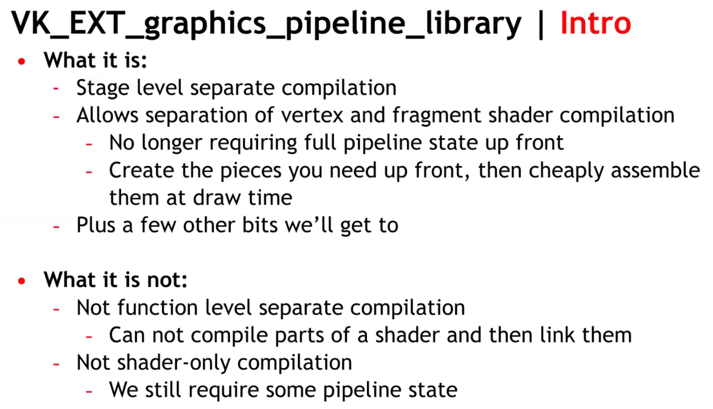
Allows separate compilation of different parts of the graphics pipeline. With this it’s now possible to split up the monolithic pipeline creation into different steps and re-use common parts shared across different pipelines.
-
Compared to monolithic pipeline state, this results in faster pipeline creation times, making this extension a good fit for applications and games that do a lot of pipeline creation at runtime.
-
Libraries are partial pipeline objects which cannot be bound directly; they are linked together to form a final executable pipeline.
-
Encourages reuse of compilation work and reduces startup/runtime stutter for games with many similar pipelines.
-
Because libraries are precompiled partial pipelines, linking is generally cheaper than compiling whole pipelines from scratch.
-
Individual pipelines stages :
-
The monolithic pipeline state has been split into distinct parts that can be compiled independently.
-
Vertex Input Interface :
-
Contains the information that would normally be provided to the full pipeline state object by VkPipelineVertexInputStateCreateInfo and VkPipelineInputAssemblyStateCreateInfo.
-
"For our engine, this information is not known until draw time, so a pipeline for this stage is still hashed and created at draw time."
-
This stage has no shader code and thus the driver can create it quickly and there are also a fairly small number of these objects.
-
-
Pre-Rasterization Shaders :
-
Contains vertex, tessellation, and geometry shader stages along with the state associated with VkPipelineViewportStateCreateInfo , VkPipelineRasterizationStateCreateInfo , VkPipelineTessellationStateCreateInfo , and VkRenderPass (or dynamic rendering).
-
The only information you actually need to create the pre-rasterization shader is the SPIR-V code and pipeline layout.
-
-
Fragment Shader :
-
Contains the fragment shader along with the state in VkPipelineDepthStencilStateCreateInfo and VkRenderPass (or dynamic rendering - although in that case only the viewMask is required).
-
If combined with dynamic rendering you can create the fragment shader pipeline with only the SPIR-V and the pipeline layout.
This allows the driver to do the heavy lifting of lowering to hardware instructions for the pre-rasterization and fragment shaders with very little information.
-
-
Fragment Output Interface :
-
Contains the VkPipelineColorBlendStateCreateInfo, VkPipelineMultisampleStateCreateInfo, and VkRenderPass (or dynamic rendering)
-
Like with the Vertex Input Interface, this stage requires information that we don’t know until draw time, so this state is also hashed and the Fragment Output Interface pipeline is created at draw time.
-
It is expected to be very quick to create and also relatively small in number.
-
-
-
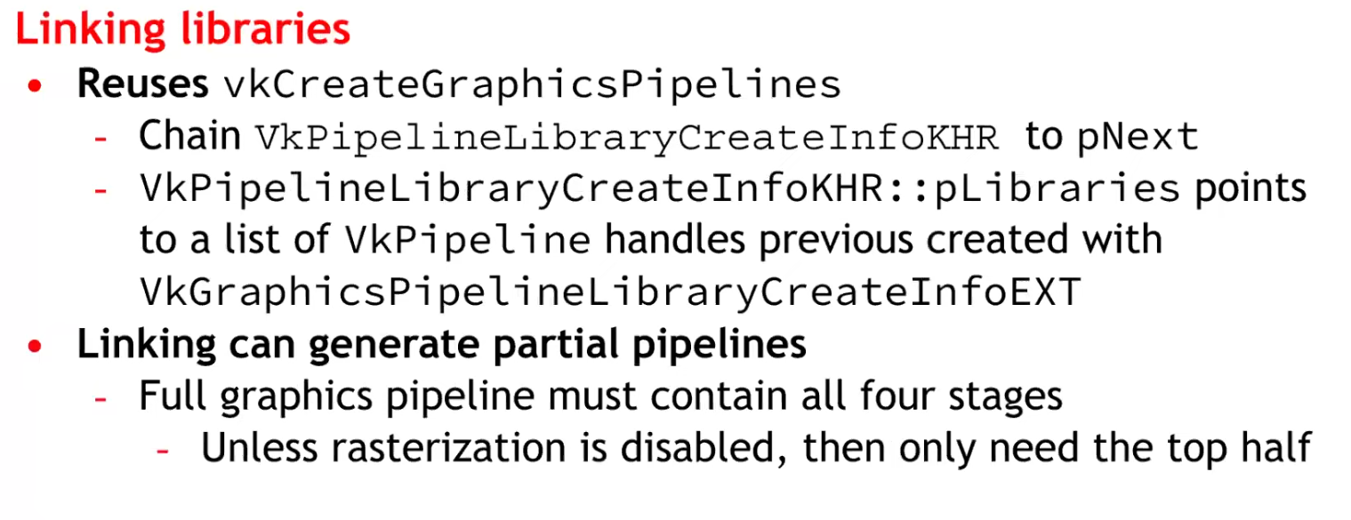
Final link :
-
With all four individual pipeline library stages created, an application can perform a final link to a full pipeline. This final link is expected to be extremely fast - the driver will have done the shader compilation for the individual stages and thus the link can be performed at draw time at a reasonable cost.
-
This is where the big benefit of the extension comes in: we’ve pre-created all of our pre-rasterization and fragment shaders, hashed the small number of vertex input/fragment output interfaces, and can on-demand create a fast linked pipeline library at draw time, thus avoiding a dreaded hitch.
-
-
If shader compilation stutter is your concern, this extension is the way to go. This extension lets you create partially-constructed PSOs (Pipeline State Objects) (e.g. one for Vertex another for Pixel Shader), and then combine them to generate the final PSO. This allows splitting the huge monolithic block into smaller monolithic blocks that are easier to handle and design around, making the API more D3D11-like (D3D11 has monolithic Rasterizer State blocks and Blend State blocks).
-
Creating pipeline libraries :
-
Creating a pipeline library (part) is similar to creating a pipeline, with the difference that you only need to specify the properties required for that specific pipeline state.
-
E.g. for the vertex input interface you only specify input assembly and vertex input state, which is all required to define the interfaces to a vertex shader.
-
VkGraphicsPipelineLibraryCreateInfoEXT library_info{}; library_info.sType = STRUCTURE_TYPE_GRAPHICS_PIPELINE_LIBRARY_CREATE_INFO_EXT; library_info.flags = GRAPHICS_PIPELINE_LIBRARY_VERTEX_INPUT_INTERFACE_EXT; VkPipelineInputAssemblyStateCreateInfo input_assembly_state = vkb::initializers::pipeline_input_assembly_state_create_info(PRIMITIVE_TOPOLOGY_TRIANGLE_LIST, 0, FALSE); VkPipelineVertexInputStateCreateInfo vertex_input_state = vkb::initializers::pipeline_vertex_input_state_create_info(); std::vector<VkVertexInputBindingDescription> vertex_input_bindings = { vkb::initializers::vertex_input_binding_description(0, sizeof(Vertex), VERTEX_INPUT_RATE_VERTEX), }; std::vector<VkVertexInputAttributeDescription> vertex_input_attributes = { vkb::initializers::vertex_input_attribute_description(0, 0, FORMAT_R32G32B32_SFLOAT, 0), vkb::initializers::vertex_input_attribute_description(0, 1, FORMAT_R32G32B32_SFLOAT, sizeof(float) * 3), vkb::initializers::vertex_input_attribute_description(0, 2, FORMAT_R32G32_SFLOAT, sizeof(float) * 6), }; vertex_input_state.vertexBindingDescriptionCount = static_cast<uint32_t>(vertex_input_bindings.size()); vertex_input_state.pVertexBindingDescriptions = vertex_input_bindings.data(); vertex_input_state.vertexAttributeDescriptionCount = static_cast<uint32_t>(vertex_input_attributes.size()); vertex_input_state.pVertexAttributeDescriptions = vertex_input_attributes.data(); VkGraphicsPipelineCreateInfo pipeline_library_create_info{}; pipeline_library_create_info.sType = STRUCTURE_TYPE_GRAPHICS_PIPELINE_CREATE_INFO; pipeline_library_create_info.flags = PIPELINE_CREATE_LIBRARY_KHR | PIPELINE_CREATE_RETAIN_LINK_TIME_OPTIMIZATION_INFO_EXT; pipeline_library_create_info.sType = STRUCTURE_TYPE_GRAPHICS_PIPELINE_CREATE_INFO; pipeline_library_create_info.pNext = &library_info; pipeline_library_create_info.pInputAssemblyState = &input_assembly_state; pipeline_library_create_info.pVertexInputState = &vertex_input_state; vkCreateGraphicsPipelines(get_device().get_handle(), pipeline_cache, 1, &pipeline_library_create_info, nullptr, &pipeline_library.vertex_input_interface); -
-
Deprecating shader modules :
-
With this extension, creating shader modules with
vkCreateShaderModulehas been deprecated and you can instead just pass the shader module create info viapNextinto your pipeline shader stage create info. This change bypasses a useless copy and is recommended. -
You can see this in the pre-rasterization and fragment shader library setup parts of the sample below.
VkShaderModuleCreateInfo shader_module_create_info{}; shader_module_create_info.sType = STRUCTURE_TYPE_SHADER_MODULE_CREATE_INFO; shader_module_create_info.codeSize = static_cast<uint32_t>(spirv.size()) * sizeof(uint32_t); shader_module_create_info.pCode = spirv.data(); VkPipelineShaderStageCreateInfo shader_Stage_create_info{}; shader_Stage_create_info.sType = STRUCTURE_TYPE_PIPELINE_SHADER_STAGE_CREATE_INFO; // Chain the shader module create info shader_Stage_create_info.pNext = &shader_module_create_info; shader_Stage_create_info.stage = SHADER_STAGE_VERTEX; shader_Stage_create_info.pName = "main"; VkGraphicsPipelineCreateInfo pipeline_library_create_info{}; pipeline_library_create_info.stageCount = 1; pipeline_library_create_info.pStages = &shader_Stage_create_info; -
-
Linking executables :
-
Once all pipeline (library) parts have been created, the pipeline executable can be linked together from them:
std::vector<VkPipeline> libraries = { pipeline_library.vertex_input_interface, pipeline_library.pre_rasterization_shaders, fragment_shader, pipeline_library.fragment_output_interface }; // Link the library parts into a graphics pipeline VkPipelineLibraryCreateInfoKHR linking_info{}; linking_info.sType = STRUCTURE_TYPE_PIPELINE_LIBRARY_CREATE_INFO_KHR; linking_info.libraryCount = static_cast<uint32_t>(libraries.size()); linking_info.pLibraries = libraries.data(); VkGraphicsPipelineCreateInfo executable_pipeline_create_info{}; executable_pipeline_create_info.sType = STRUCTURE_TYPE_GRAPHICS_PIPELINE_CREATE_INFO; executable_pipeline_create_info.pNext = &linking_info; executable_pipeline_create_info.flags = PIPELINE_CREATE_LINK_TIME_OPTIMIZATION_EXT; VkPipeline executable = NULL_HANDLE; vkCreateGraphicsPipelines(get_device().get_handle(), thread_pipeline_cache, 1, &executable_pipeline_create_info, nullptr, &executable);-
This will result in the pipeline state object to be used at draw time.
-
A note on
PIPELINE_CREATE_LINK_TIME_OPTIMIZATION_EXT: This is an optimization flag. If specified, implementations are allowed to do additional optimization passes. This may increase build times but can in turn result in lower runtime costs.
-
-
Independent Descriptor Sets :
-
Imagine a situation where the vertex and fragment stage accesses two different descriptor sets.
// Vertex Shader layout(set = 0) UBO_X; // Fragment Shader layout(set = 1) UBO_Y;-
Normally when compiling a pipeline, both stages are together and internally a driver will reserve 2 separate descriptor slots for
UBO_XandUBO_Y. When using graphics pipeline libraries, the driver will see the fragment shader only uses a single descriptor set. It might internally map it toset 0, but when linking the two libraries, there will be a collision. ThePIPELINE_LAYOUT_CREATE_INDEPENDENT_SETS_EXTflag ensures the driver will be able to handle this case and not have any collisions. There are some extra constraints when using this flag, but the Validation Layers will detect them for you.
-
-
-
 .
.
-
 .
.
-
Same number of pipelines, but acquired through reuse, instead of recompilation.
-
Think of the link step as additive, instead of multiplicative.
-
-
 .
.
-
 .
.
-
Considerations :
-
At the time it was said there would be an impact on CPU.
-
It was unknown whether it was compatible with mobile or not.
-
No libraries were made for Geometry and Tessellation Shaders, as they are difficult.
-
-
~One pipeline per shader variant
-
It is the cause of the problem listed above.
-
Causes a combinatorial explosion of variants.
Single pipeline, branch inside shader (material ID / push constant)
-
No way, seems horrible.
Optimizations
Pipeline Cache, with
VkPipelineCache
-
It allows the driver to reuse previously computed pipeline artifacts across pipeline creations (and you can persist cache data between runs).
-
Avoids repeating expensive driver work; shortens startup time by reusing previously compiled artifacts.
-
Creating a Vulkan pipeline requires compiling
VkShaderModuleinternally. This will have a significant increase in frame time if performed at runtime. To reduce this time, you can provide a previously initialisedVkPipelineCacheobject when calling thevkCreateGraphicsPipelinesorvkCreateComputePipelinesfunctions. This object behaves like a cache container which stores the pipeline internal representation for reuse. In order to benefit from using aVkPipelineCacheobject, the data recorded during pipeline creation needs to be saved to disk and reused between application runs. -
Vulkan allows an application to obtain the binary data of a
VkPipelineCacheobject and save it to a file on disk before terminating the application. This operation can be achieved using two calls to thevkGetPipelineCacheDatafunction to obtain the size andVkPipelineCacheobject’s binary data. In the next application run, theVkPipelineCachecan be initialised with the previous run’s data. This will allow thevkCreateGraphicsPipelinesorvkCreateComputePipelinesfunctions to reuse the baked state and avoid repeating costly operations such as shader compilation. -
How to use it :
-
Create one
VkPipelineCachefor related pipeline creation operations (often one per device). -
Pass it into
vkCreateGraphicsPipelinesfor every create call. -
On exit (or periodically) call
vkGetPipelineCacheDataand write to disk; on startup feed that blob intovkCreatePipelineCacheto prepopulate the cache.
-
-
KHR_pipeline_binary-
VkPipelineCacheobjects were designed to enable a Vulkan driver to reuse blobs of state or shader code between different pipelines. Originally, the idea was that the driver would know best which parts of state could be reused, and applications only needed to manage storage and threading, simplifying developer code. -
Over time however,
VkPipelineCacheobjects proved to be too opaque, prompting the Vulkan Working Group to release a number of extensions to provide more application control over them. The current capabilities ofVkPipelineCacheobjects satisfies many applications, but has shortcomings in more advanced use cases. -
Previous difficulties :
-
The
VkPipelineCacheAPI provides no control over the lifetime of the binary objects that it contains. An application wanting to implement an LRU cache, for example, has a hard time usingVkPipelineCacheobjects. -
Some applications maintain a cache of VkPipeline objects. The VkPipelineCache API makes it impossible to efficiently associate the cached binary objects within a VkPipelineCache object with the application’s own cache entries.
-
-
What’s more, most drivers maintain an internal cache of pipeline-derived binary objects. In some cases, it would be beneficial for the application to directly interact with that internal cache, especially on some specialized platforms.
-
The new
KHR_pipeline_binaryextension introduces a clean new approach that provides applications with access to binary blobs and the information necessary for optimal caching, while smoothly integrating with the application’s own caching mechanisms. -
It’s worth noting that the
EXT_shader_objectextension already includes analogous functionality toKHR_pipeline_binary. The two extensions were worked on concurrently to provide a universally available solution, including devices where theEXT_shader_objectextension cannot yet be supported. -
Applications that do not need the advanced functionality of the new KHR_pipeline_binary extension can continue to use VkPipelineCache objects for their simplicity and optimized implementation. But developers that are not satisfied with the VkPipelineCache API should read on to learn more about this powerful new approach.
-
Article .
-
Read up to 'Caching With KHR_pipeline_binary'.
-
-
Optimizing the Shader with
KHR_buffer_device_address
-
See Vulkan#Physical Storage Buffer (KHR_buffer_device_address) .
-
Support :
-
.
-
Pipeline derivatives
-
A creation mechanism to tell the driver that one pipeline is a parent and others are children (derivatives).
-
The driver may avoid redoing expensive compile/link steps and reuse intermediate data from the parent, reducing creation time.
-
The intent is faster creation of children by reusing work/data from the parent.
-
The pipeline creation API provides no way to tell it what state will change. The idea being that, since the implementation can see the parent's state, and it can see what you ask of the child's state, it can tell what's different.
-
Is it worth it? NO.
-
TLDR :
-
No vendor is actually recommending the use of pipeline derivatives, except maybe to speed up pipeline creation.
-
-
Tips and Tricks: Vulkan Dos and Don’ts .
-
Don’t expect speedup from Pipeline Derivatives.
-
-
Vulkan Usage Recommendations , Samsung
-
Pipeline derivatives let applications express "child" pipelines as incremental state changes from a similar "parent"; on some architectures, this can reduce the cost of switching between similar states.
-
Many mobile GPUs gain performance primarily through pipeline caches, so pipeline derivatives often provide no benefit to portable mobile applications.
-
Recommendations:
-
Create pipelines early in application execution. Avoid pipeline creation at draw time.
-
Use a single pipeline cache for all pipeline creation.
-
Write the pipeline cache to a file between application runs.
-
Avoid pipeline derivatives.
-
-
-
Vulkan Best Practice for Mobile Developers - Pipeline Management , Arm Software, Jul 11, 2019
-
Don't create pipelines at draw time without a pipeline cache (introduces performance stutters).
-
Don't use pipeline derivatives as they are not supported.
-
-
Vulkan Samples, LunarG - API-Samples/pipeline_derivative/pipeline_derivative.cpp
-
This sample creates pipeline derivative and draws with it. Pipeline derivatives should allow for faster creation of pipelines.
-
In this sample, we'll create the default pipeline, but then modify it slightly and create a derivative.
-
The derivative will be used to render a simple cube. We may later find that the pipeline is too simple to show any speedup, or that replacing the fragment shader is too expensive, so this sample can be updated then.
-
-
-
Typical use case :
-
Many pipelines that differ only by a few fields (e.g., different specializations or small state changes).
-
-
How to use :
-
Create a base pipeline with
PIPELINE_CREATE_ALLOW_DERIVATIVES. -
For similar pipelines (small shader or state differences), create child pipelines with
PIPELINE_CREATE_DERIVATIVEand setbasePipelineHandleorbasePipelineIndexpointing to the base.
-
-
How it affects the pipeline workflow :
-
Can materially reduce pipeline creation cost when many similar pipelines are needed.
-
Useful at runtime if you must create many variants quickly.
-
Still creates separate pipeline objects (state memory + driver bookkeeping).
-
-
Not guaranteed to be implemented with identical performance gains on all drivers; behavior is driver-dependent.